Flexural vibration element and electronic component
a flexural vibration and electronic component technology, applied in the field of flexural vibration elements, can solve the problems of mechanical loss, deformation so as to suppress the vibration leakage of the vibrating arms toward the outside, and improve the performance of the flexural vibration elemen
- Summary
- Abstract
- Description
- Claims
- Application Information
AI Technical Summary
Benefits of technology
Problems solved by technology
Method used
Image
Examples
first embodiment
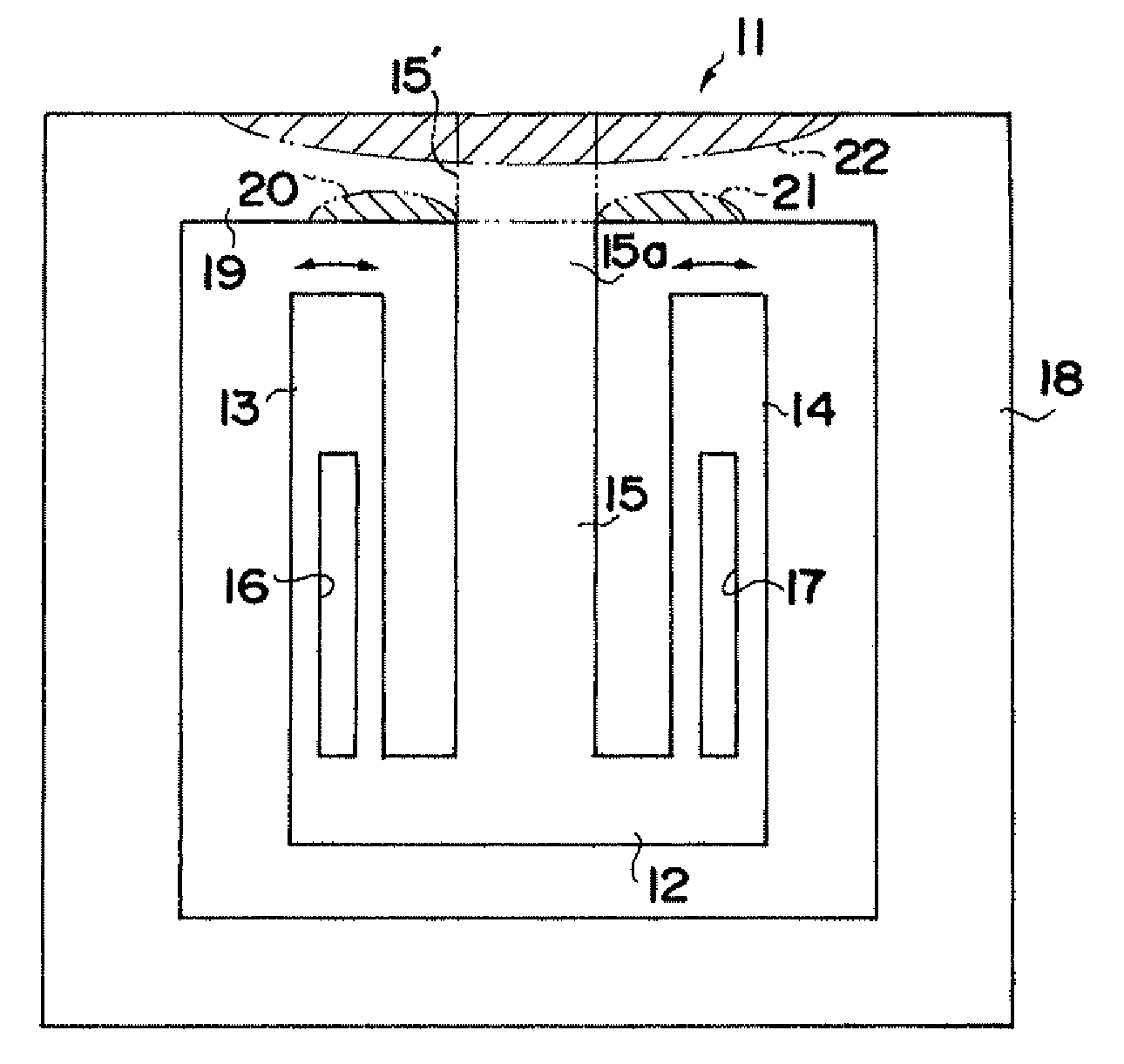
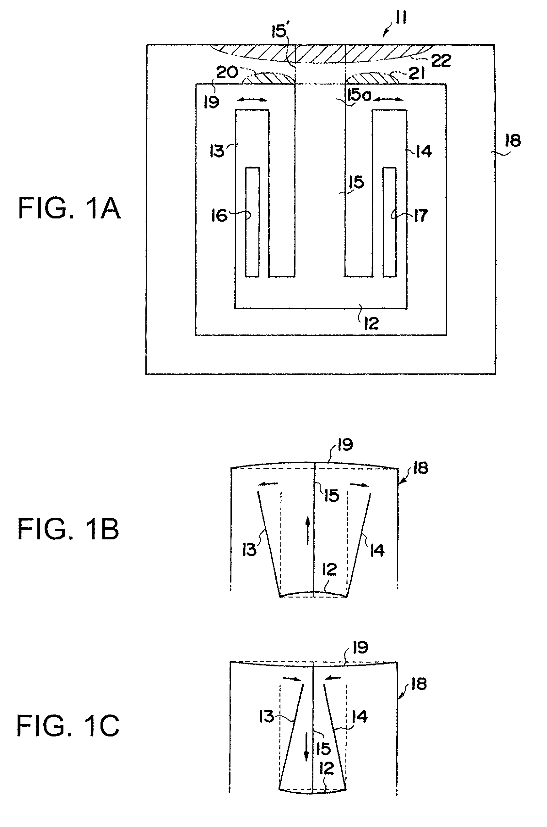
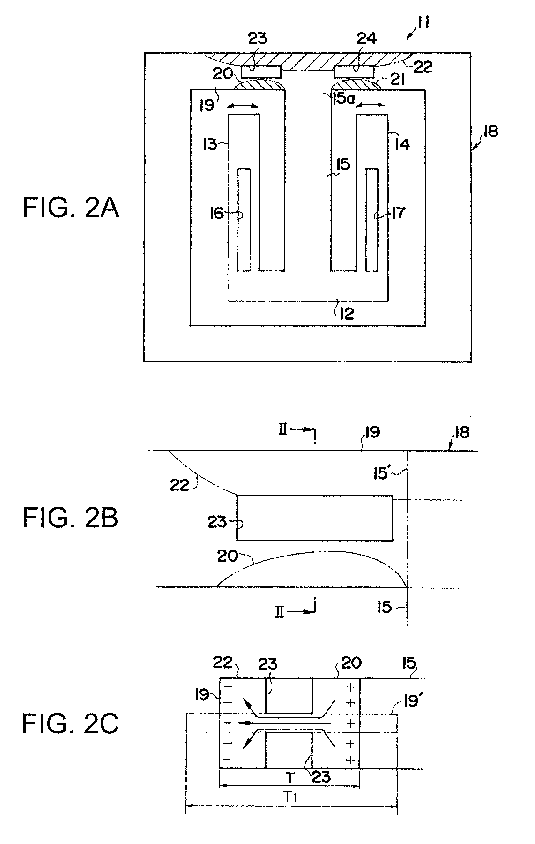
[0046]FIG. 1A is a schematic view showing a structure of a piezoelectric vibration element, according to a first embodiment, to which the present invention is applied. A piezoelectric vibration element 11 according to the first embodiment includes a vibration element body composed of a connecting part 12, two vibrating arms 13 and 14 which extend from the connecting part 12 in parallel, and one central supporting arm 15. The central supporting arm 15 extends from the connecting part 12 between the vibrating arms 13 and 14 in parallel with the arms 13 and 14 at equal distance from the arms 13 and 14. A linearly shaped long groove 16 is formed on each of a front surface and a rear surface of the vibrating arm 13 and a linearly shaped long groove 17 is formed on each of a front surface and a rear surface of the vibrating arm 14, so as to control a crystal impedance (CI) value.
[0047]The piezoelectric vibration element 11 further includes a frame body 18 having a rectangular shape and di...
second embodiment
[0067]FIG. 5A is a schematic view showing a structure of a piezoelectric vibration element, according to a second embodiment, to which the present invention is applied. In a similar manner to the first embodiment, a piezoelectric vibration element 41 according to the second embodiment includes a vibration element body composed of a connecting part 42, two vibrating arms 43 and 44 which extend from the connecting part 42 in parallel, and one central supporting arm 45. The central supporting arm 45 extends from the connecting part 42 between the vibrating arms 13 and 14 in parallel with the arms 13 and 14 at equal distance from the arms 13 and 14. A linearly shaped long groove 46 is formed on each of a front surface and a rear surface of the vibrating arm 43 and a linearly shaped long groove 47 is formed on each of a front surface and a rear surface of the vibrating arm 44, so as to control a crystal impedance (CI) value.
[0068]The piezoelectric vibration element 41 further includes a ...
first modification
of Second Embodiment
[0074]FIGS. 6A to 6D show a first modification of the second embodiment. A piezoelectric vibration element 41 of the first modification differs from the piezoelectric vibration element 41 of the second embodiment at a point that the element of the first modification has grooves 57, 58, 59, and 60 along the supporting part 49. The grooves 57, 58, 59, and 60 are respectively disposed between the part 50 at the inner side, in the width direction, of the supporting part 49 and the part 52 at the outer side of the same, between the part 51 at the inner side and the part 52, between the part 53 at the inner side and the part 55, and between the part 54 at the inner side and the part 56 at the outer side, at equal distance from peripheries of the supporting part 49. As described according to the second embodiment above, compressive stress and tensile stress occur alternately at the supporting part 49 due to the flexural vibration of the vibrating arms 43 and 44.
[0075]FI...
PUM
 Abstract
Description
Claims
Application Information
 - R&D
- Intellectual Property
- Life Sciences
- Materials
- Tech Scout
- Unparalleled Data Quality
- Higher Quality Content
- 60% Fewer Hallucinations
Browse by: Latest US Patents, China's latest patents, Technical Efficacy Thesaurus, Application Domain, Technology Topic, Popular Technical Reports.
© 2025 PatSnap. All rights reserved.Legal|Privacy policy|Modern Slavery Act Transparency Statement|Sitemap|About US| Contact US: help@patsnap.com


