
Method and apparatus for driving light emitting elements for projection of images

a technology of light emitting elements and projection methods, applied in the field of methods and apparatus for projection of images, can solve the problems of other colors in brightness and reduced overall performance, and achieve the effect of simple driving scheme of light emitting elements and stable image color quality

Active Publication Date: 2010-07-08
SIGNIFY HLDG BV
View PDF14 Cites 31 Cited by
  • Summary
  • Abstract
  • Description
  • Claims
  • Application Information

AI Technical Summary

Benefits of technology

[0006]The present invention aims to provide a method and apparatus providing a simple light emitting element driving scheme resulting in a stable image color quality.SUMMARY OF THE INVENTION
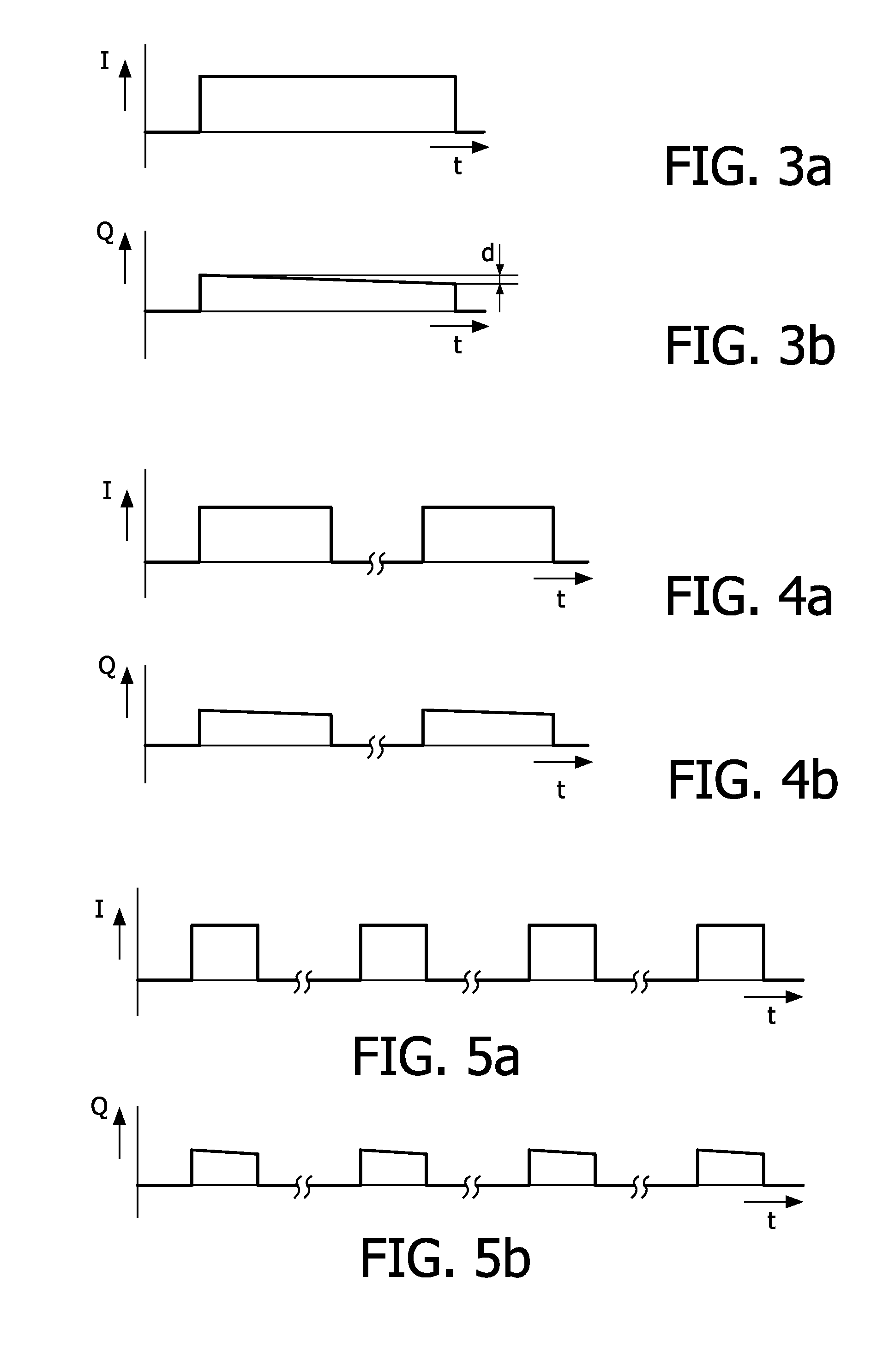
[0008]G, and a third light emitting element, B. Each light emitting element has a duty cycle in a lighting period, e.g. an image frame period. The method comprises: providing a sequence scheme for alternatingly driving different ones of the light emitting elements; and driving the light emitting elements according to said sequence scheme at least two times in said lighting period, while maintaining said duty cycle for each light emitting element. Here, a duty cycle is defined as a percentage indicating the ratio of a time period of applying a drive pulse, and the time period of repetition of the drive pulse. With such a driving of the light emitting elements, each light emitting element may be switched on for such a short period that it will not heat up completely during the drive pulse. The drive pulse duration is chosen small compared to the thermal time constant of the light emitting element, which reduces temperature effects on the brightness of the light emitted by the light emitting element. The fact that each light emitting element may be switched on for such a short period that it will not heat up completely during the drive pulse may also be used to allow a higher drive current without exceeding the maximum temperature of the light generating area of the light emitting element. Of course, it is also possible to save current while maintaining brightness.
[0009]According to an embodiment of the invention, in said sequence scheme, at least one light emitting element is driven more times than another one. Thus, the one or more light emitting elements that have a relatively high temperature sensitivity, such as a red light emitting element, receive a relatively high number of pulses with a relatively short duration, thereby further reducing a heating of the light emitting element while retaining an average light output.

Problems solved by technology

This is undesirable.
However, this requires a feedback control of the light emitting element driving means, and the storage of data regarding a temperature dependency of the light output of the light emitting elements.
Additionally, since the maximum light output of a display device is limited by the maximum brightness of its weakest source, the control has to reduce the other colors in brightness, and overall performance is reduced.

Method used


Image

  • Method and apparatus for driving light emitting elements for projection of images
  • Method and apparatus for driving light emitting elements for projection of images
  • Method and apparatus for driving light emitting elements for projection of images

Examples


Embodiment Construction

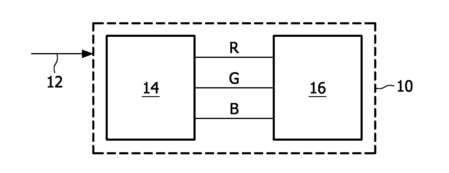
[0028]FIG. 1 schematically illustrates a projection system 10 using light emitting elements of different primary colors. An image data input 12 receives image data which are processed in the projection system by a driver circuit 14, which provides drive signals for different light emitting elements producing different primary colors such as red, green and blue colors for generating an image, or a sequence of images (video) in a projection apparatus 16 comprising the different light emitting elements and a display. The projection apparatus 16 may comprise one or more lenses, one or more mirrors, one or more digitally controlled micromirror devices (DMD), one or more liquid crystal devices (LCD) or thin film transistors (TFT), one or more liquid crystal on silicon devices (LcoS), and the like.

[0029]An example of such a projection system is the digital light processing (DLP®) technology by Texas Instruments.

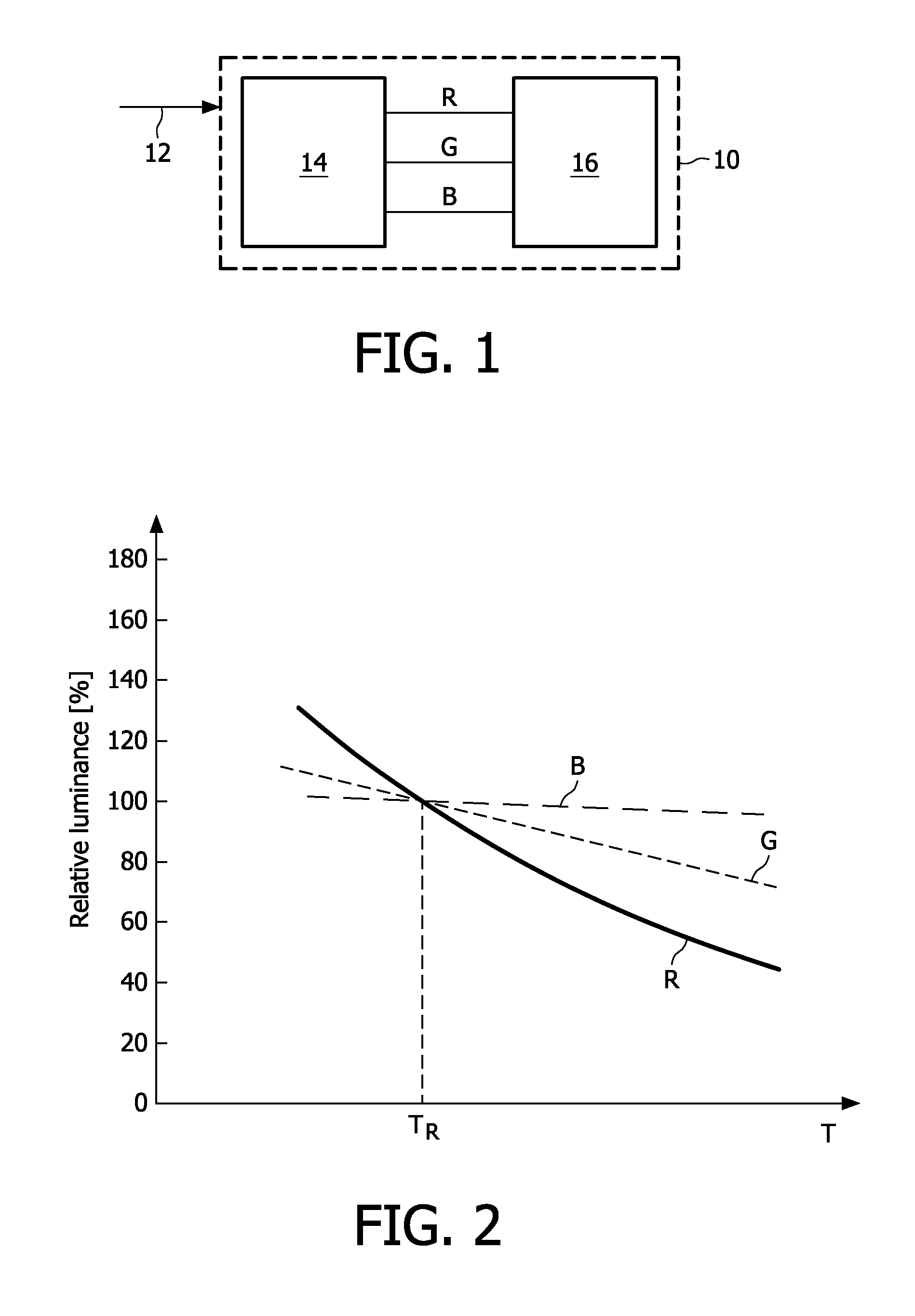
[0030]FIG. 2 illustrates relationships between the temperature (indicted by T) ...


PUM


Abstract

A light source sequentially emits lights generated by at least three light emitting elements each emitting a different primary color to generate an image. Each light emitting element has a duty cycle in a lighting period, which may be an image frame period. A sequence scheme is provided for alternatingly driving different ones of the light emitting elements. The light emitting elements are driven in accordance with the sequence scheme at least two times in the lighting period, while maintaining the duty cycle for each light emitting element. In the sequence scheme, at least one light emitting element having the highest temperature sensitivity of all light emitting elements is driven more times than another one.

Description

FIELD OF THE INVENTION[0001]The present invention relates to a method and apparatus for projection of images by sequentially emitting lights from at least three light emitting elements each emitting a different primary color.BACKGROUND OF THE INVENTION[0002]An image projection apparatus uses at least three light emitting elements emitting primary colors (conventionally: red, green and blue, but not limited thereto) for displaying an image. The image may be a still image or a moving image (video) constructed of a sequence of (still) images. In order to create a video of sufficient quality for the human eye, a sequence frequency must be sufficiently high, where conventionally an image sequence rate for moving pictures of 24 Hz (film), 25 Hz (film on PAL standard, and some video), 30 Hz (film converted to NTSC standard), 50 Hz (video in PAL, often interlaced), 60 Hz (video in NTSC standard, often interlaced, frequently used in computer graphics) is used depending on the adopted standar...

Claims


Application Information

Patent Timeline
IPC IPC(8): G09G5/10H05B37/02
CPCG09G3/3413G09G2310/0235
Inventor OTTE, ROBDEPPE, CARSTENDEURLOO, OSCAR JAN
Owner SIGNIFY HLDG BV
Learn More