Image display device

a technology of image display and display tube, which is applied in the direction of instruments, optics, gas-filled discharge tubes, etc., can solve the problems of short life span, inability to achieve conventional products, and possibility of bursting, so as to prevent an increase in its size and power loss, and efficiently control the temperature

Active Publication Date: 2010-07-08
PANASONIC CORP
View PDF10 Cites 44 Cited by
  • Summary
  • Abstract
  • Description
  • Claims
  • Application Information

AI Technical Summary

Benefits of technology

[0015]According to the present invention, it is possible to provide an image display device provided with a cooling system capable of efficiently controlling the temperatures of a plurality of

Problems solved by technology

Further, in the case of high pressure mercury lamps in particular, they have maintenance-related problems, such as a short life span (several thousand hours) and the possibility of bursting.
Although the light output of LEDs may not be sufficient, the level of chromaticity of each color of light is unique, which may not be achieved by conventional products.
On th

Method used


Image

  • Image display device
  • Image display device
  • Image display device

Examples


embodiment 1

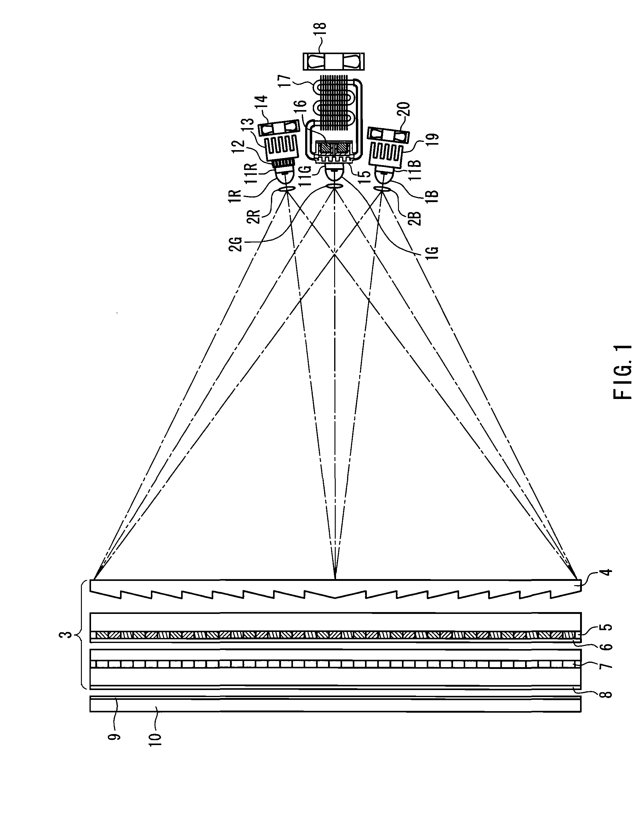
[0074]FIG. 1 shows a configuration of an image display device according to Embodiment 1 of the present invention. In this device, LED modules for emitting R, G and B colors of light, namely, a red LED module 1R, a green LED module 1G and a blue LED module 1B are provided.

[0075]Although it is not shown in the drawing, the LED modules 1R, 1G and 1B for the respective colors of light as solid light sources have a configuration in which an LED die is mounted on a metal substrate for dissipating heat, with an electric insulation layer being interposed between the die and the substrate. Further, the LED die is connected to an LED driving power supply through an electrode, and a converging lens is placed in front of the LED die.

[0076]Light outputted from the red LED module 1R passes through an illumination optical system 2R and is guided to an optical modulator 3. Similarly to the red light, light outputted from the green LED module 1G passes though an illumination optical system 2G and is...

embodiment 2

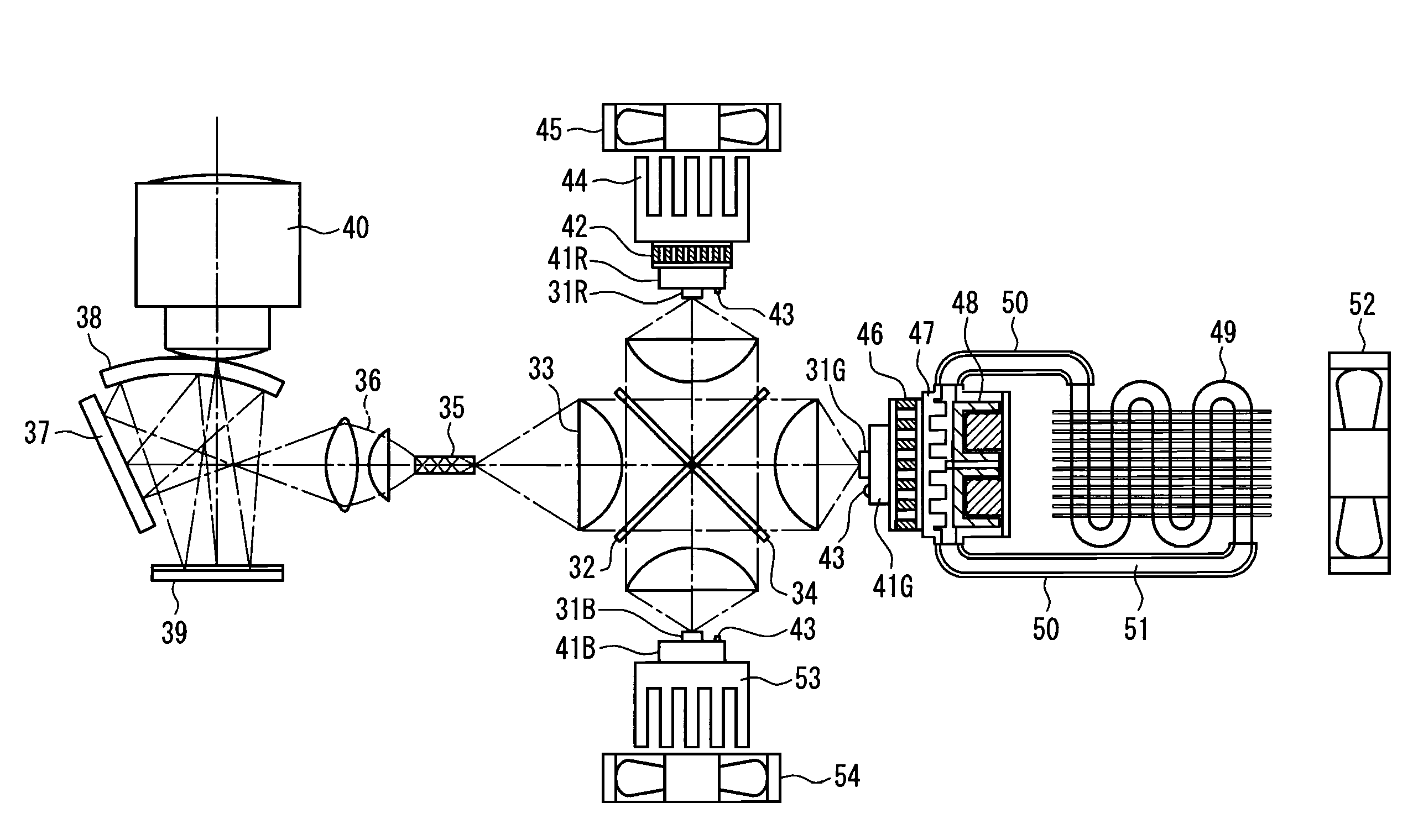
[0103]FIG. 4 shows a configuration of an image display device according to Embodiment 2 of the present invention. This image display device is a projection-type image display device having a projection optical system. In this device, LED modules for R, G and B colors of light, namely, a red LED module 31R, a green LED module 31G and a blue LED module 31B are provided.

[0104]Although it is not shown in the drawing, the LED modules 31R, 31G and 31B for the respective colors of light as solid light sources have a configuration in which an LED die is mounted on a metal substrate for dissipating heat with an insulation layer being interposed between the die and the substrate. The LED die is connected to an LED driving power supply through an electrode, and a converging lens is placed in front of the LED die.

[0105]Light outputted from the red LED module 31R enters a red reflecting dichroic mirror 32, and is reflected by the mirror to enter a condensing optical system 33. Light outputted fr...


PUM


Abstract

LED modules 1R, 1G, 1B for respectively emitting red, green and blue colors of light, illumination optical systems 2R, 2G and 2B for guiding light from the LED modules, and a liquid crystal panel 7 for modulating the light from the LED modules guided by the illumination optical systems on the basis of an image signal are placed. The LED modules are provided with respective cooling units connected to the backside thereof through spreaders 11R, 11G and 11B as thermal conductive members. Only the cooling device for the red LED module 1R is formed by using a red Peltier device 12 as a thermoelectric element capable of controlling heating and absorbing heat. Efficient temperature control by appropriately using a Peltier device for cooling the plurality of solid light sources that emit colors of light different from each other becomes possible, and an increase in the size of the cooling system and power losses can be suppressed.

Description

TECHNICAL FIELD[0001]The present invention relates to image display devices that display images by irradiating an image display element with light from a plurality of solid light sources, and in particular to an image display device including a cooling unit using a thermoelectric element for cooling the plurality of solid light sources.BACKGROUND ART[0002]Conventionally, white light sources, such as a cold cathode tube and a high pressure mercury lamp, have been utilized as light sources for image display devices. In a direct view image display device such as a liquid crystal monitor, red, green and blue colors of light that is wavelength-selected by a color filter, which is made of a material that absorbs unnecessary wavelength light from white light from the light source, is guided to liquid crystal elements for red, green and blue signals.[0003]Further, in a projection type image display device such as a projector, white light is separated into red, green and blue colors of light...

Claims


Application Information

Patent Timeline
IPC IPC(8): G03B21/16H01J7/24
CPCG03B21/16
Inventor YAMAGISHI, SHIGEKAZUTANABE, KAZUNORINANBA, SHUU
Owner PANASONIC CORP
Why Eureka
Try Eureka