Information recording medium, reproduction apparatus and recording apparatus

a technology of information recording medium and reproduction apparatus, which is applied in the direction of digital signal error detection/correction, instruments, recording signal processing, etc., can solve the problems of opcs that cannot obtain optimal recording power exert adverse effects on the recording/reproduction signal quality, and may not be able to achieve optimal recording power derived by opcs in such information recording layers. , to achieve the effect of preventing damage, high-precision recording power adjustmen

Inactive Publication Date: 2010-07-08
PANASONIC CORP
View PDF20 Cites 4 Cited by
  • Summary
  • Abstract
  • Description
  • Claims
  • Application Information

AI Technical Summary

Benefits of technology

[0069]As described above, according to the present invention, first, laser beam power adjustment is performed using the first test recording area. After the power adjustment, a recording parameter other than the power, such as the pulse waveform or the like is performed using the second test recording area. Since the second test recording area is used after the power adjustment, the second test recording area can be prevented from being damaged. Owing to this, the test recording areas of a plurality of information recording layers can be located at radial positions overlapping each other. Thus, the zone having a limited size can be effectively used.
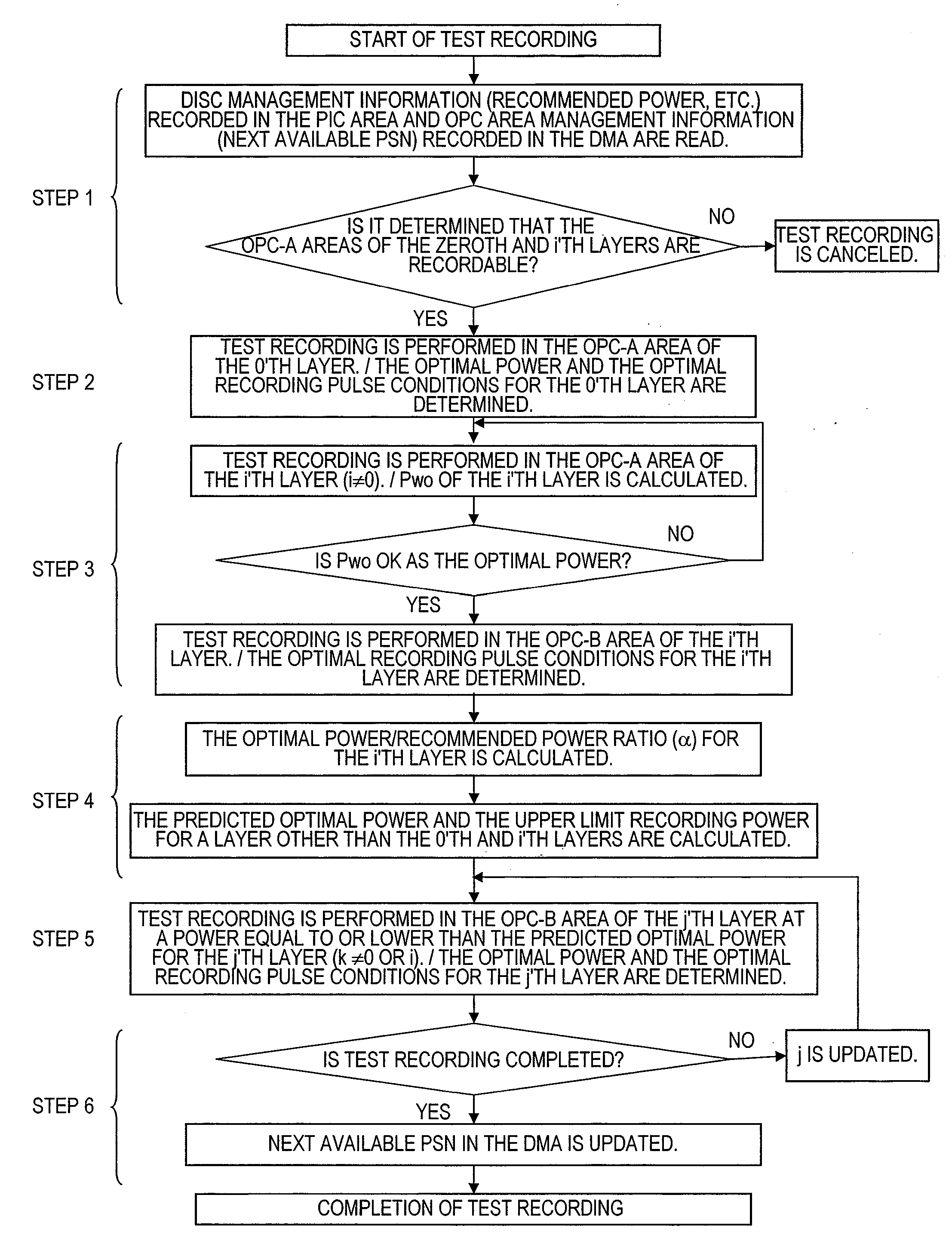
[0070]According to the present invention directed to a multilayer optical information recording medium, and a recording method, a reproducing method and a recording / reproducing apparatus for a multilayer optical information recording medium, the following is realized. For performing test recording in an OPC area in each of a plurality of information recording layers of an multilayer optical disc including the plurality of information recording layers in order to adjust the recording power or the write strategy to be optimal, highly precise recording power adjustment and write strategy adjustment are realized even in an information recording layer far from the laser beam incidence side regardless of the recording state of an information recording layer close to the laser beam incidence side. As a result, a highly reliable multilayer optical disc can be provided.
[0071]By arranging the physical format of the test recording areas in a devised manner, the physical size of the OPC areas of the information recording layers can be increased within a limited inner zone or outer zone. Therefore, highly reliable recording power adjustment and write strategy adjustment are realized without decreasing the number of times of test recording. Especially for an optical disc on which recording can be done only once, for example, a write-once optical disc, such a situation can be avoided that the OPC areas are used up although the user data zone is not full. Thus, the problem that, for example, the recording cannot be performed on the optical disc merely because test recording cannot be performed can be solved.
[0072]As a result, a large capacity and high density multilayer optical information recording medium is realized while a highly reliable information recording / reproducing apparatus is realized.

Problems solved by technology

When test recording is performed in an OPC area of an information recording layer close to the laser beam incidence side at an excessively high recording power, the laser beam which is transmitted through such an information recording layer is influenced by the recording state of the OPC area to exert an adverse effect on the recording / reproduction signal quality of an information recording layer farther from the laser beam incidence side.
Nonetheless, in the case where the OPC areas in the odd-numbered or even-numbered information recording layers are overlapped with each other, light which has been transmitted through an information recording layer close to the light incidence side is influenced by the recording state of such a layer and exerts an adverse effect on the recording or reproduction signal quality of an information recording layer farther from the light incidence side.
As a result, the optimal recording power may not be derived by the OPC in such an information recording layer far from the light incidence side.
As understood from these, the above-described problems have not been solved.
When this occurs, there may be a high possibility that the recording to an optical disc needs to be stopped for the reason that test recording cannot be performed despite the user data zone is not full.

Method used


Image

  • Information recording medium, reproduction apparatus and recording apparatus
  • Information recording medium, reproduction apparatus and recording apparatus
  • Information recording medium, reproduction apparatus and recording apparatus

Examples


embodiment 1

[0126]Hereinafter, a physical format, especially, positional arrangement of OPC areas, of a multilayer optical disc according to Embodiment 1 of the present invention will be described with reference to the drawings.

[0127]FIG. 3 shows an example of a physical format of OPC areas in each information recording layer according to Embodiment 1 of the present invention. FIG. 3 shows an example of a physical format, especially, positional arrangement of the OPC areas of the optical disc medium 101 including four information recording layers. The zeroth information recording layer (L0) is located farthest from the laser beam incidence side, and the first information recording layer (L1) is located closer, than the zeroth information recording layer, to the laser beam incidence side. The second information recording layer (L2) and the third information recording layer (L3) are sequentially located from the side of the first information recording layer toward the laser beam incidence side. T...

embodiment 2

[0147]FIG. 4 shows an example of a physical format of OPC areas in each information recording layer according to Embodiment 2 of the present invention. Unlike the multilayer optical disc in Embodiment 1, as shown in FIG. 4, the OPC-B area of each of L1 through L3 is partially located overlapped with the PIC area of the zeroth information recording layer, and the physical size of the OPC-B area is larger than the physical size of the OPC-A area in the same information recording layer, respectively.

[0148]Recording is not performed in the OPC-B area at an excessively high recording power. Therefore, when reproducing data from the PIC area of L0, the light beam passing through the OPC-B areas of L1 through L3 is scattered or diffracted and thus can suppress the decline of the quality of the PIC area reproduction signal.

[0149]By arranging the physical format of the test recording areas in a devised manner as described above, the OPC areas can be located in the information recording layer...

embodiment 3

[0152]FIG. 5 shows an example of a physical format of OPC areas in each information recording layer according to Embodiment 3 of the present invention. As shown in FIG. 5, L0 includes only one test recording area (OPC-A area), whereas L1 through L3 each include two test recording areas, i.e., the OPC-A area and the OPC-B area. The OPC-B area of each of L1 through L3 is partially overlapped with the PIC area of L0. Recording is not performed in the OPC-B area at an excessively high recording power. Therefore, when reproducing data from the PIC area of L0, the light beam passing through the OPC-B areas of L1 through L3 is scattered or diffracted and thus can suppress the decline of the quality of the PIC area reproduction signal. The OPC-A areas of L1 through L3 are located at generally the same radial position in an overlapped manner with one another. The physical size of the OPC-A area of L0 is larger than the physical size of the OPC-A area in each of L1 through L3.

[0153]By arrangi...


PUM

PropertyMeasurementUnit
wavelengthaaaaaaaaaa
distanceaaaaaaaaaa

Abstract

An information recording medium according to the present invention includes three or more information recording layers. Each of the plurality of information recording layers includes a test recording area usable for adjusting a recording condition. One of the plurality of information recording layers includes a reproduction-only management data area in which management data usable for managing the information recording medium is pre-recorded. Each of the other two or more information recording layers among the plurality of information recording layers includes a test recording area at a radial position partially overlapping the radial position of the management data area.

Description

[0001]This application is a Continuation-in-Part of U.S. patent application Ser. No. 12 / 258,562 filed on Oct. 27, 2008 and claims priority under 35 U.S.C. §119 to U.S. Provisional Application No. 61 / 118,698, filed Dec. 1, 2008, both of which are incorporated herein by reference in their entirety.BACKGROUND OF THE INVENTION[0002]1. Field of the Invention[0003]The present invention relates to a multilayer optical information recording medium including a plurality of information recording layers each having a test recording area (OPC area) usable for finding an optimal recording condition (recording power and / or write strategy), and a recording apparatus and a reproducing apparatus for performing recording on and / or reproduction from the multilayer optical information recording medium.[0004]2. Description of the Related Art[0005]Conventionally, there are standards for optical recording mediums such as BD-R, BD-RE, DVD-RAM, DVD-R, DVD-RW, CD-RW and the like, and there are technologies f...

Claims


Application Information

Patent Timeline
Patent Type & Authority Applications(United States)
IPC IPC(8): G11B7/26G11B20/18
CPCG11B7/00736G11B2007/0013G11B7/24038G11B7/1267
Inventor NAKAMURA, ATSUSHIMIYAGAWA, NAOYASUFURUMIYA, SHIGERUHINO, YASUMORIITO, MOTOSHISHOJI, MAMORUTAKAHASHI, YOSHIHISA
Owner PANASONIC CORP
Why Eureka
Try Eureka