Method and apparatus for writing

a writing apparatus and writing method technology, applied in the field of writing methods and writing apparatuses, can solve the problems of not being able to reduce the time sufficiently, take a long time, etc., and achieve the effect of efficient calculation of the exposure dos

Active Publication Date: 2010-07-08
NUFLARE TECH INC
View PDF1 Cites 23 Cited by
  • Summary
  • Abstract
  • Description
  • Claims
  • Application Information

AI Technical Summary

Benefits of technology

[0010]An object of the present invention is to provide a pattern writing apparatus capable of more efficiently calculating an exposure dose where a proximity effect and a fogging effect have been corrected, and a method therefor.
[0011]In accordance with one aspect of the present invention, a writing method includes calculating a proximity effect-corrected dose for correcting a proximity effect in charged particle beam writing, for each first mesh region made by virtually dividing a writing region of a target object into a plurality of first mesh regions of a first mesh size, calculating a fogging effect-corrected dose by using the proximity effect-corrected dose calculated and an area density in the first mesh size with respect to a part of a calculation region for calculating the fogging effect-corrected dose for correcting a fogging effect in the charged particle beam writing, and by using an area density in a second mesh size larger than the first mesh size with respect to a remaining part of the calculation region, synthesizing the fogging effect-corrected dose and the proximity effect-corrected dose for the each first mesh region, and writing a pattern on the target object by using a charged particle beam based on a synth...

Problems solved by technology

However, when calculating an influence of the fogging effect whose influence range is larger, it would take a long time if the influence of the proximity effect is calculated for each of all the regions each time.
Therefore, even though the ...

Method used


Image

  • Method and apparatus for writing
  • Method and apparatus for writing
  • Method and apparatus for writing

Examples


embodiment 1

[0021]In the following Embodiments, there is described a structure using an electron beam as an example of a charged particle beam. However, the charged particle beam is not limited to the electron beam. Other charged particle beam, such as an ion beam, may also be used.

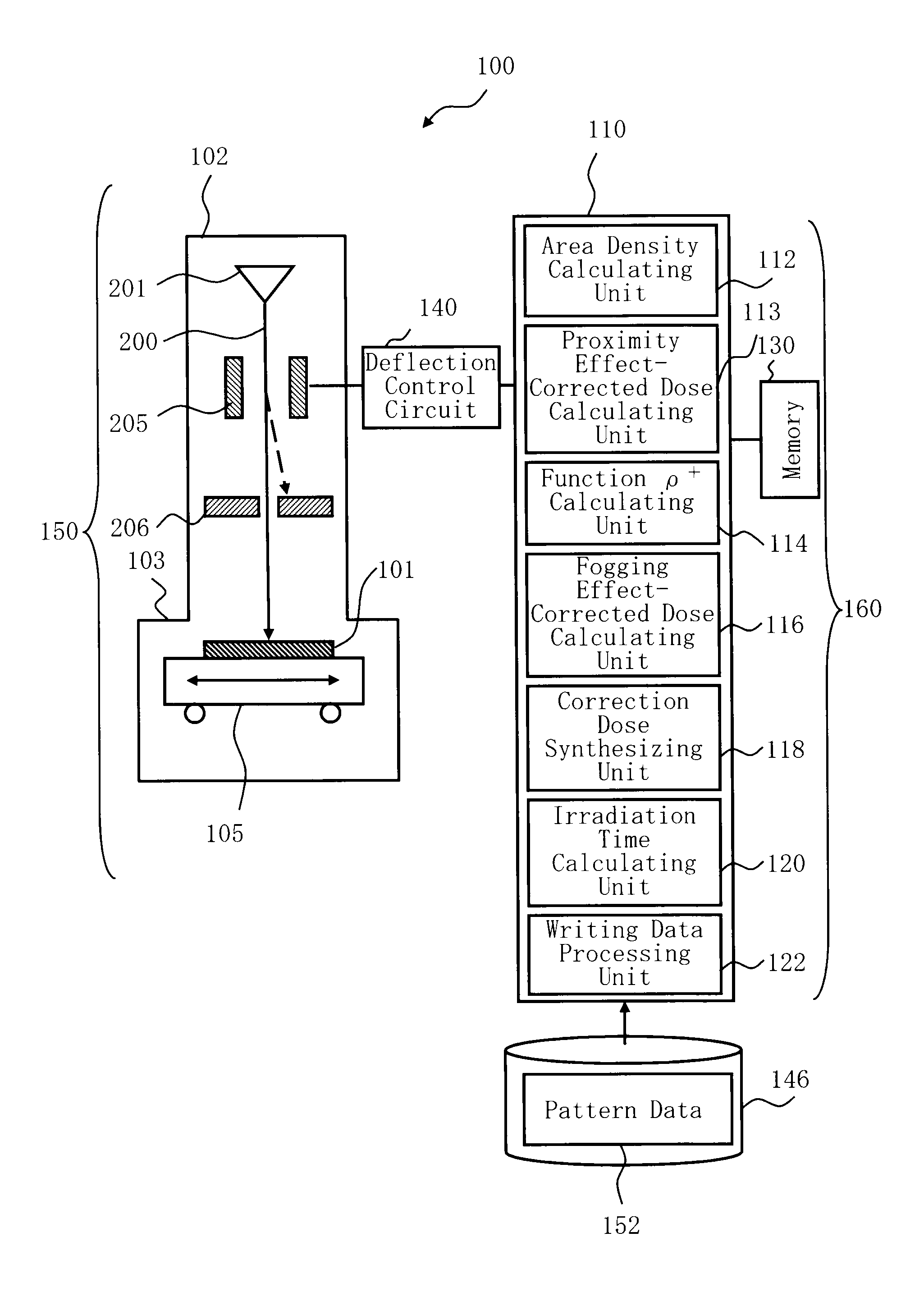
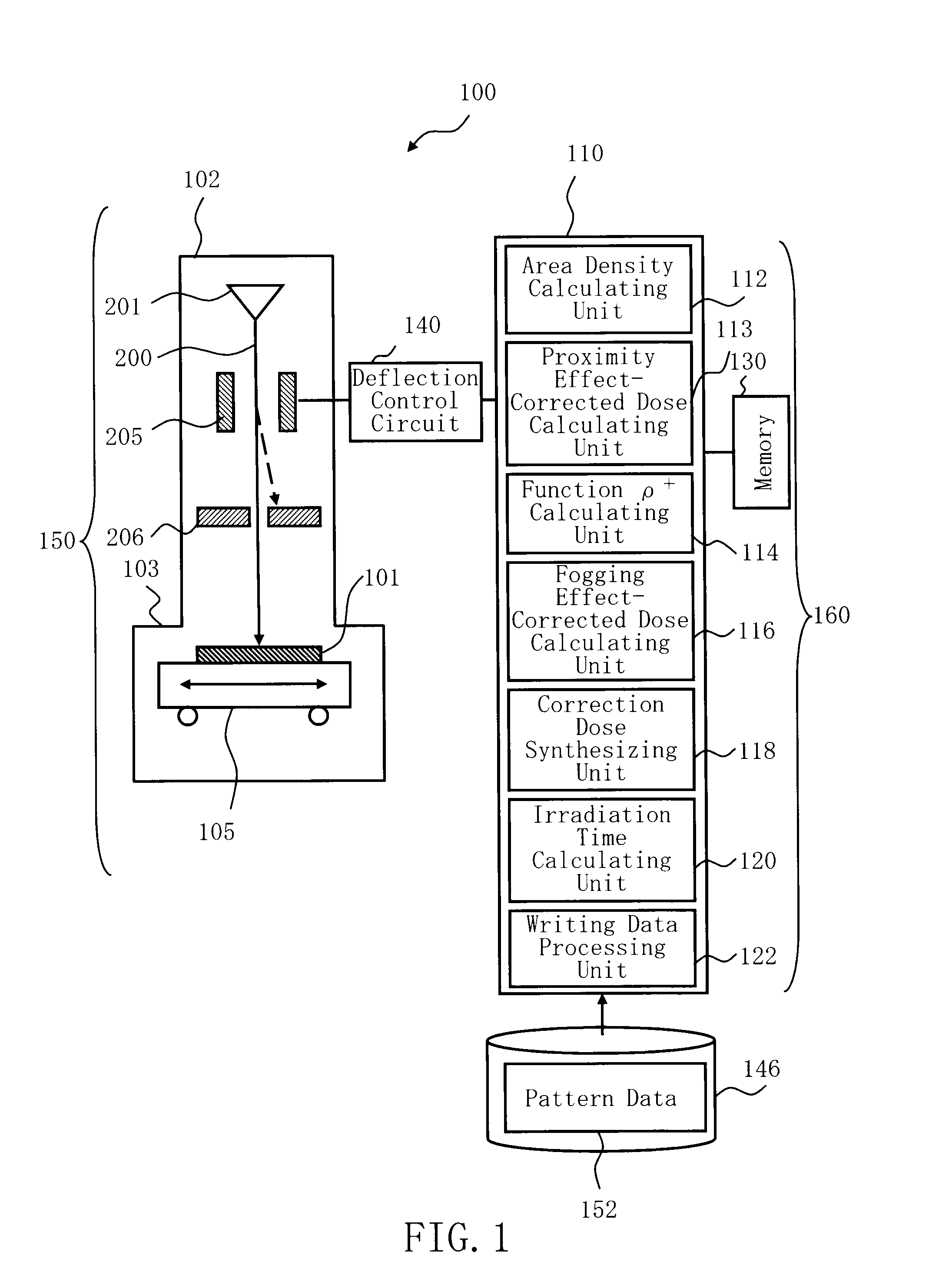
[0022]FIG. 1 is a schematic diagram showing an example of the main part structure of a writing apparatus according to Embodiment 1. In FIG. 1, a writing apparatus or “lithography apparatus”100 includes a writing unit 150 and a control unit 160. The writing apparatus 100 is an example of a charged particle beam writing apparatus. The writing unit 150 includes an electron lens barrel 102 and a writing chamber 103. In the electron lens barrel 102, there are arranged an electron gun assembly 201, a blanking (BLK) deflector 205, and a blanking (BLK) aperture 206. In the writing chamber 103, there is arranged an XY stage 105. The control unit 160 includes a control computer 110, a memory 130 serving as an example of a stor...


PUM


Abstract

A writing method includes calculating a proximity effect-corrected dose for correcting a proximity effect in charged particle beam writing, for each first mesh region made by virtually dividing a writing region of a target object into a plurality of first mesh regions of a first mesh size, calculating a fogging effect-corrected dose by using the proximity effect-corrected dose calculated and an area density in the first mesh size with respect to a part of a calculation region for calculating the fogging effect-corrected dose for correcting a fogging effect in the charged particle beam writing, and by using an area density in a second mesh size larger than the first mesh size with respect to a remaining part of the calculation region, synthesizing the fogging effect-corrected dose and the proximity effect-corrected dose for the each first mesh region, and writing a pattern on the target object by using a charged particle beam based on a synthesized correction dose.

Description

CROSS-REFERENCE TO RELATED APPLICATION[0001]This application is based upon and claims the benefit of priority from the prior Japanese Patent Application No. 2009-000729 filed on Jan. 6, 2009 in Japan, the entire contents of which are incorporated herein by reference.BACKGROUND OF THE INVENTION[0002]1. Field of the Invention[0003]The present invention relates to a writing method and a writing apparatus. For example, it relates to an electron beam writing apparatus which can correct an exposure dose, and to a writing method thereof.[0004]2. Description of Related Art[0005]Microlithography technique that advances microminiaturization of semiconductor devices is extremely important and the unique process of forming a pattern in semiconductor manufacturing. In recent years, with high integration of large-scale integrated circuits (LSI), a line width (critical dimension) required for semiconductor device circuits is shrinking year by year. In order to form a desired circuit pattern on suc...

Claims


Application Information

Patent Timeline
IPC IPC(8): G03F7/20G21K5/00G21K1/00
CPCB82Y10/00B82Y40/00H01J37/3174G21K1/025G03F7/2061G03F1/68
Inventor KATO, YASUOYASHIMA, JUNMATSUMOTO, HIROSHIMOTOSUGI, TOMOOIIJIMA, TOMOHIROABE, TAKAYUKI
Owner NUFLARE TECH INC
Why Eureka
Try Eureka