

Tool changer for machine tools
a technology for machine tools and tools, applied in the field of tool changers for machine tools, can solve the problems of very time-consuming movements, and achieve the effect of saving space and energy consumption
- Summary
- Abstract
- Description
- Claims
- Application Information
AI Technical Summary
Benefits of technology
Problems solved by technology
Method used
Image

Examples
Embodiment Construction
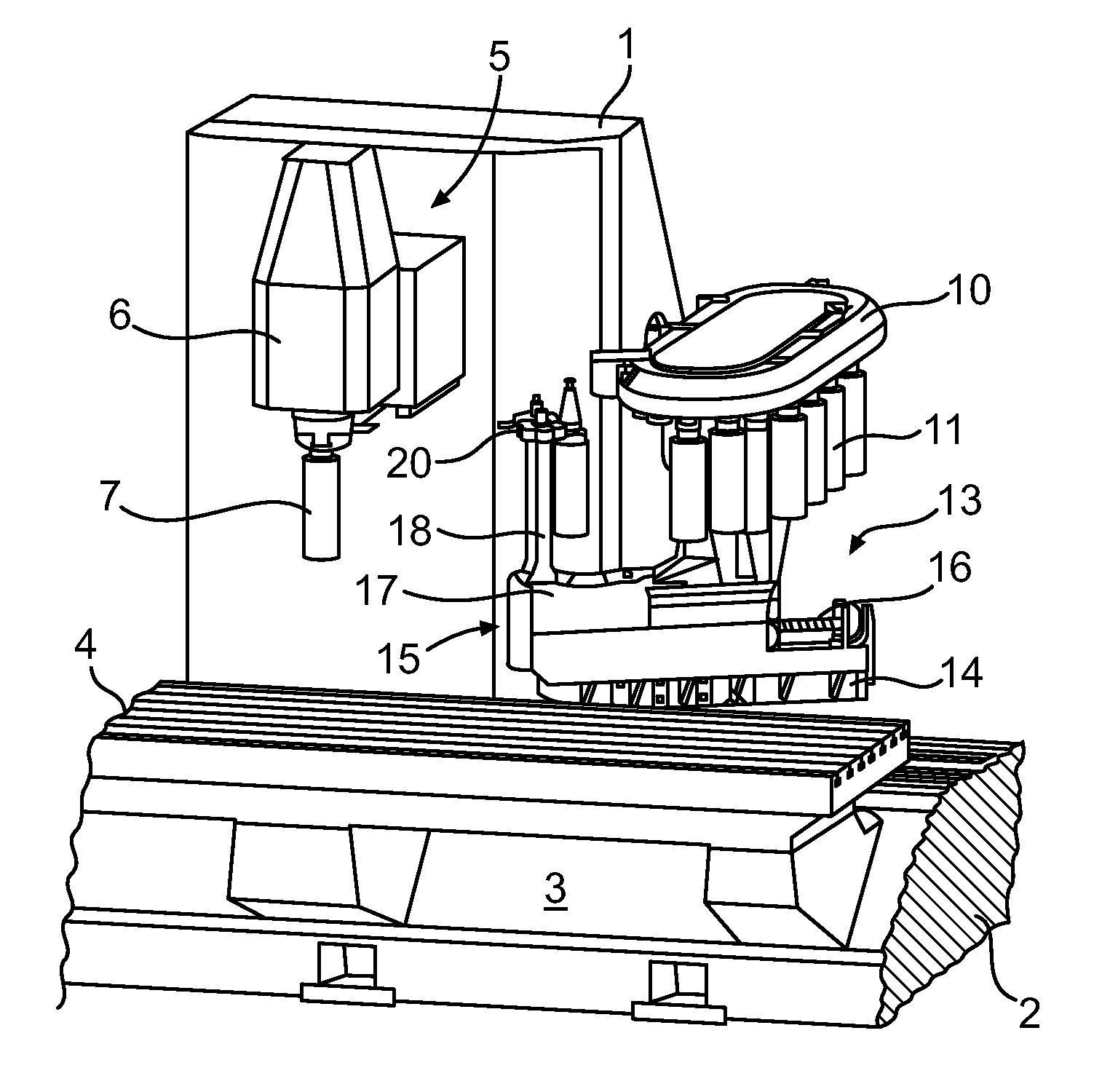
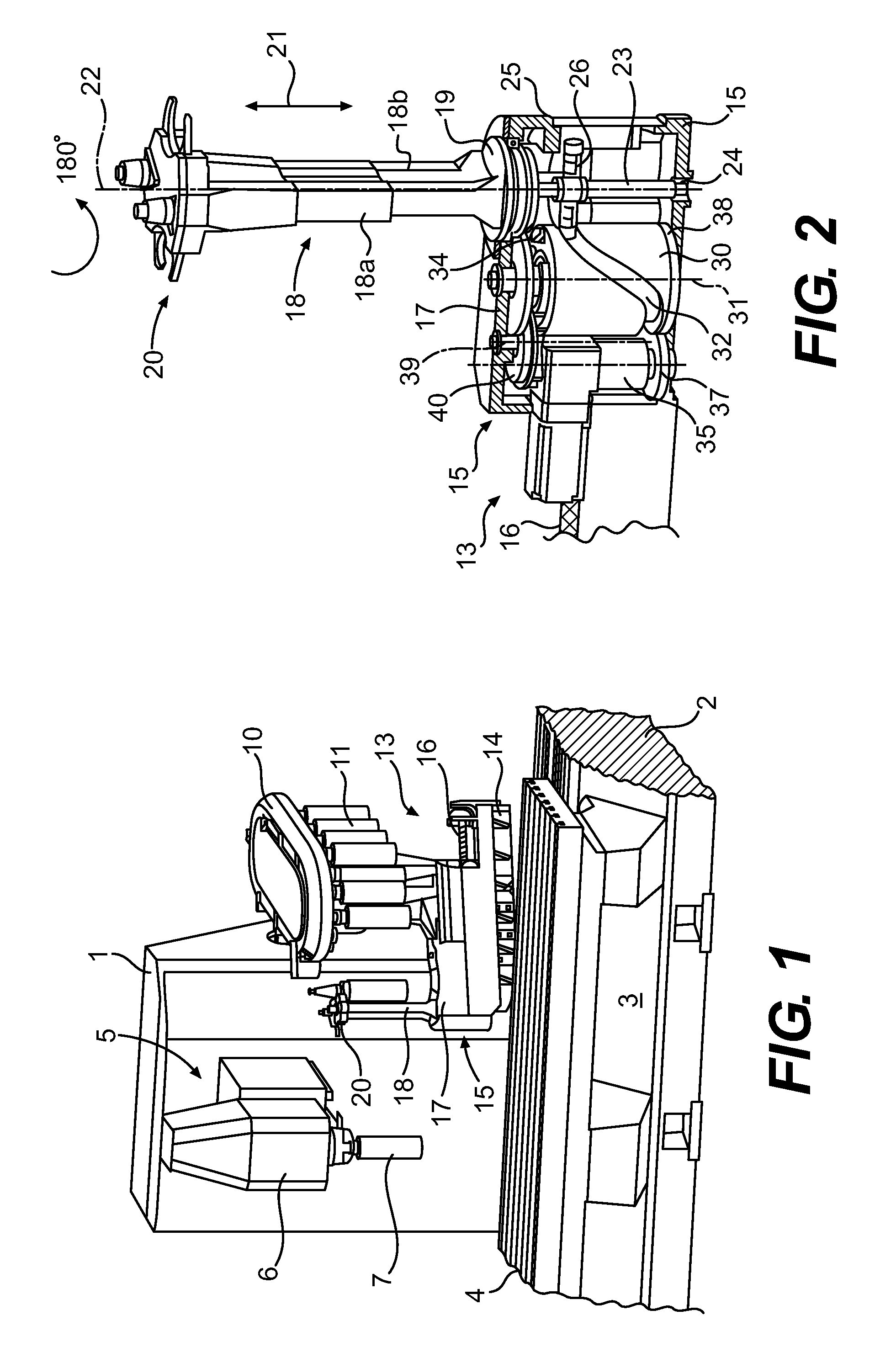
[0005]It is a purpose of the invention to provide a tool changer for machine tools whose mechanical cam gear is structured in a technically simple and compact manner, which has low inertias so that only relatively small driving powers are required and which allows a fast change of tools while reducing the tool change cycle times.
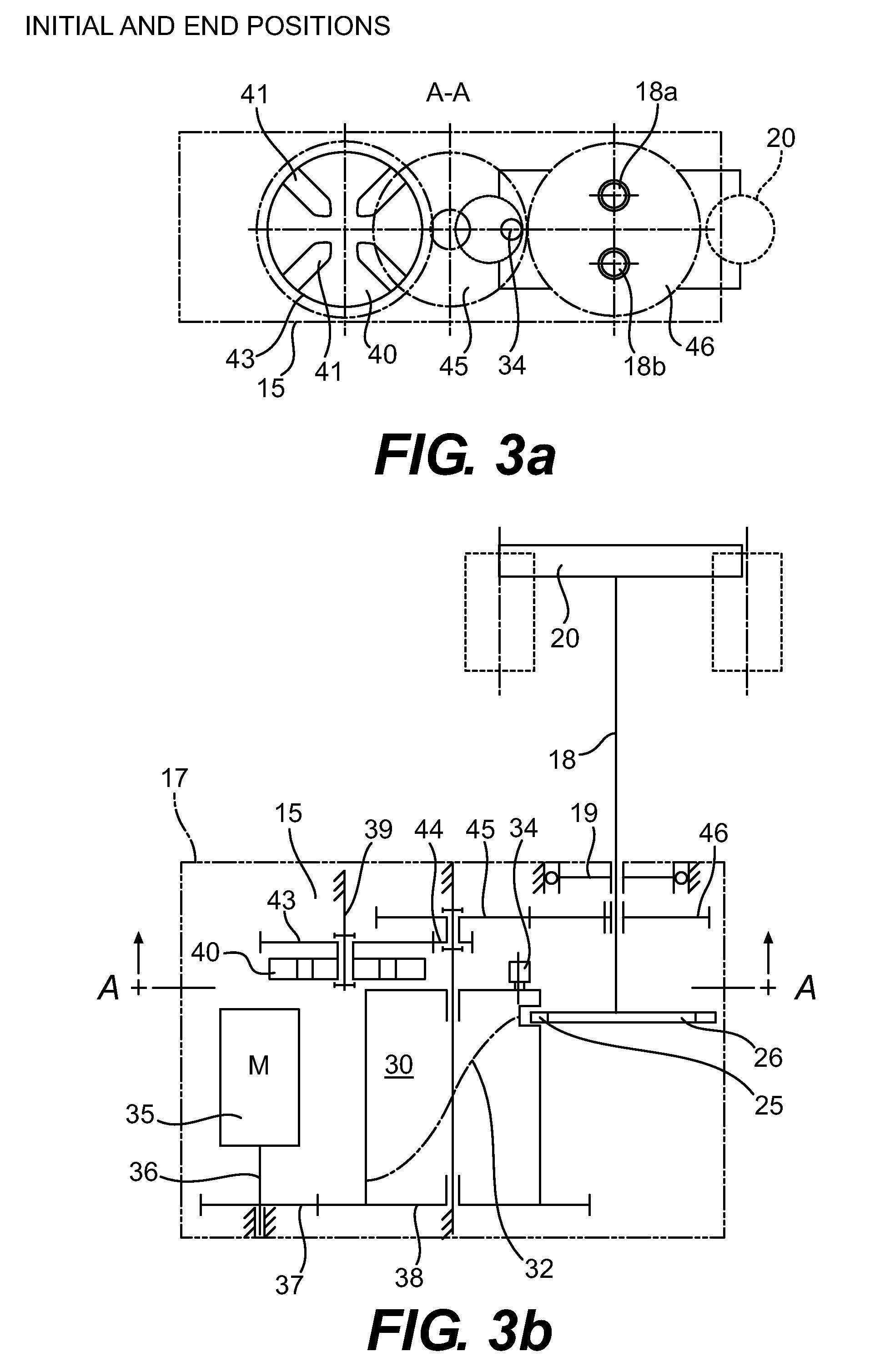
[0006]According to embodiments of the invention, this purpose results, at least in pat, from the fact that the cam barrel of the mechanical cam gear has a tappet for the rotational drive of the tool gripper on the upper front and a cam curve for the lifting movement of the tool gripper on its circumference, that the tappet engages with a Maltese wheel supported on a shaft which is parallel to the rotational axis of the tool gripper, and the supporting column of the tool gripper, the cam barrel and the Maltese wheel are successively arranged with rotational axes parallel to the axis.
[0007]The arrangement of the gear members of the lifting and pivoting gear on...
PUM
 Abstract
Description
Claims
Application Information