
Programmable controller

a controller and programmable technology, applied in the field of programmable controllers, can solve the problems of requiring considerable time, requiring a certain amount of time to switch from the operating state to the stop state, and not always fixed cycle time value, so as to increase the throughput of the control target device, increase the efficiency, and increase the effect of speed

Active Publication Date: 2010-07-08
ORMON CORP
View PDF7 Cites 19 Cited by
  • Summary
  • Abstract
  • Description
  • Claims
  • Application Information

AI Technical Summary

Benefits of technology

[0014]Nowadays, due to complication, an increase in speed, etc., of control target devices, there is a tendency to seek the optimization of the value of fixed cycle time itself to increase the throughput of the control target devices to increase productivity.
[0019]The present invention has been devised to solve the problems described above, and an object thereof is to provide a programmable controller capable of adjusting the value of fixed cycle time to an optimum value in a short period of time.
[0040]Moreover, since the above-described change operation to the fixed cycle time can be performed with the control target device maintaining an operating state (test run), unlike traditional programmable controllers, there is no need to switch the control target device between an operating state and a stop state every time a change operation is performed. Accordingly, there is also no need to perform time-consuming pre-processing operations which are associated with switching from an operating state to a stop state, enabling to accomplish the optimization of the fixed cycle time in a short period of time.
[0051]According to such a configuration, when, for example, a user program is partially rewritten (added) by online editing, the setting can be automatically changed to fixed cycle time that is suitable for a new user program obtained after the rewrite, which saves the user from having to perform an operation to rewrite the fixed cycle time each time an online editing operation is performed.
[0056]In each of the above-described operating modes, control to selectively allow a change to a user program in a peripheral service process can be easily implemented by, for example, selectively performing a process for a relevant rewrite instruction command in each mode in the above-described operating unit responding process.

Problems solved by technology

As is well known by those skilled in the art, during operation of a programmable controller, the value of cycle time is not always fixed between cycles due to various factors.
This is based on consideration of design that forcefully terminating the system process being performed rather causes inconveniences.
In addition, in a recent programmable controller that connects a programmable display, a remote I / O device, a plurality of other programmable controllers, etc., over a network, it may be difficult, due to various event interrupts, etc., to uniquely estimate the value of actual cycle time only by the size of a user program installed on the programmable controller.
Therefore, the switching from the operating state to the stop state normally requires some amount of time.
Hence, in a conventional programmable controller, to optimize the value of fixed cycle time, the control target device side repeats switching between an operating state and a stop state again and again, causing a problem that a considerable amount of time is required.

Method used


Image

  • Programmable controller
  • Programmable controller
  • Programmable controller

Examples


Embodiment Construction

[0075]Hereinafter, a preferred embodiment of a programmable controller system according to the present invention will be described in detail with reference to the accompanying drawings.

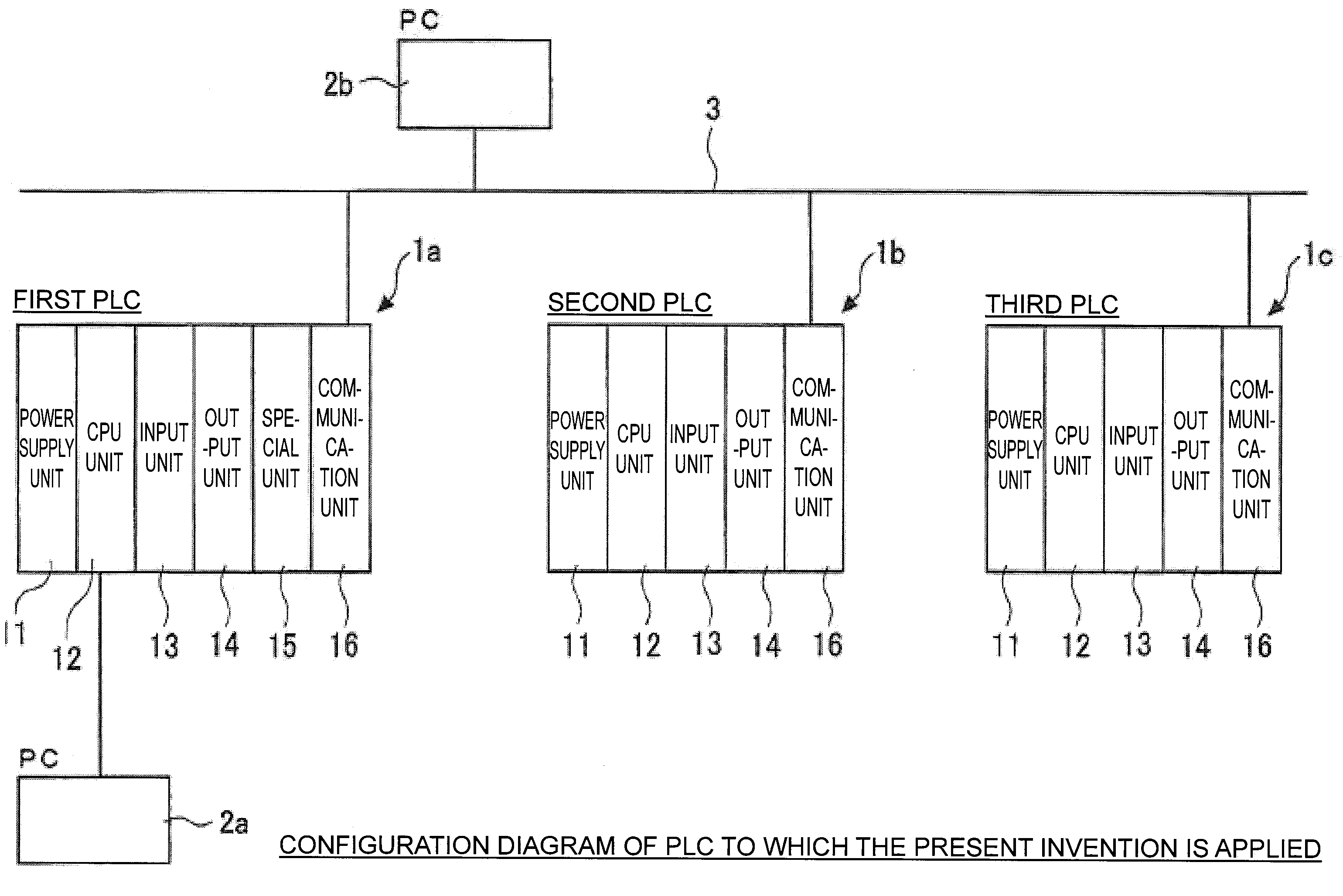
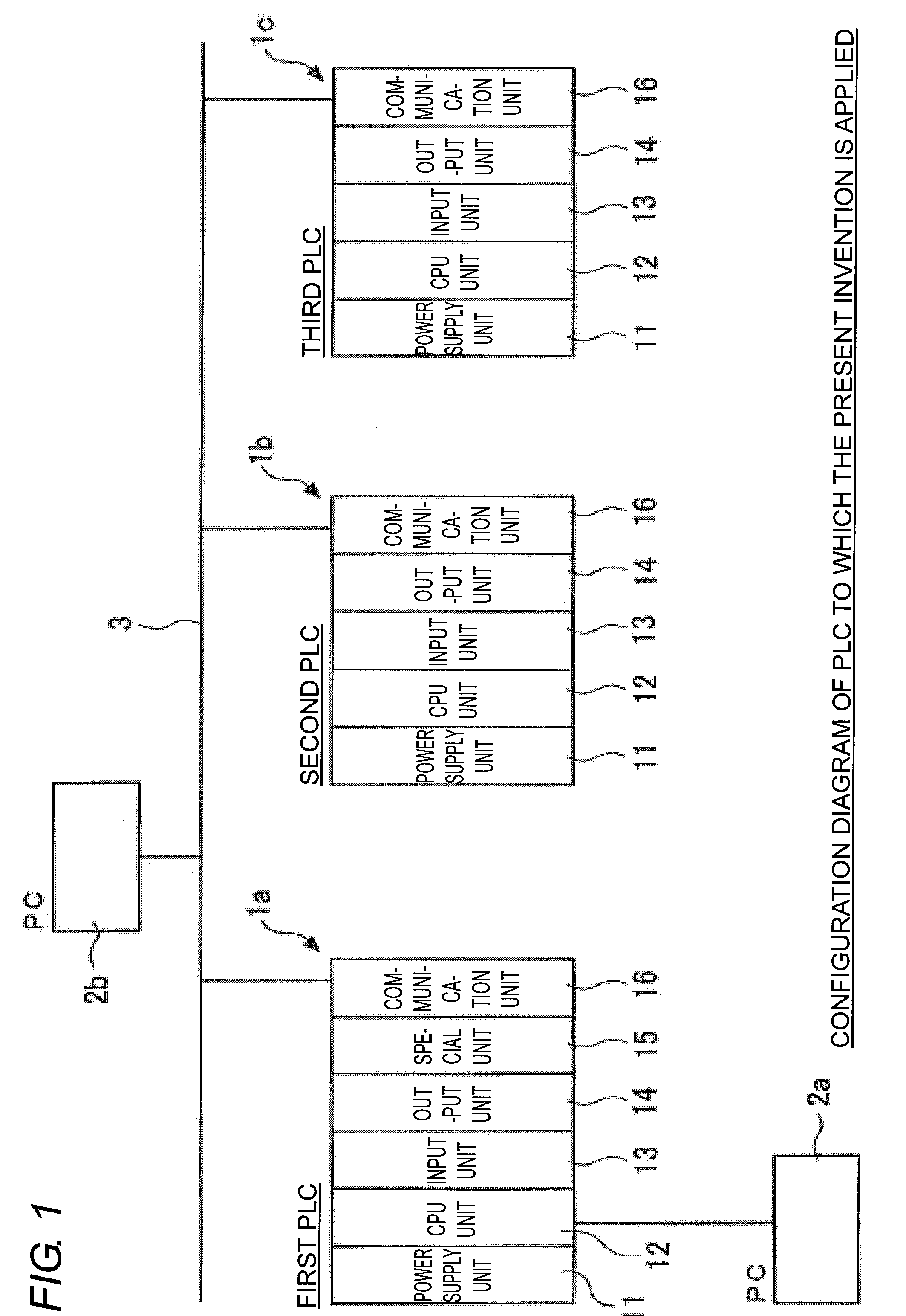
[0076]A configuration diagram of a PLC system to which the present invention is applied is shown in FIG. 1. The system includes a plurality of PLCs 1 and a PC 2b which are connected to each other over a network 3. Each of the PLCs 1 includes a power supply unit 11, a CPU unit 12, an input unit 13, an output unit 14, a special unit 15, and a communication unit 16. A PC 2a and the CPU unit 12 may be directly connected to each other to allow data communication therebetween. The power supply unit 11 is a unit that supplies power to the entire PLC 1. The CPU unit 12 is a unit that controls the entire PLC. When some input is made from a control target device, an input signal corresponding to the input is obtained through the input unit 13 and is processed by the CPU unit 12. When the PLC 1 controls the cont...


PUM


Abstract

The value of fixed cycle time is adjusted to an optimum value in a short period of time. In a second operational mode (MON) of a PLC, a series of a plurality of system processes are repeatedly performed with a change to a user program in a peripheral service process being allowed. A change to fixed cycle time to be compared with actual cycle time is prohibited in a first operational mode (RUN) but is allowed in the second operational mode (MON) and a non-operational mode (PRG).

Description

BACKGROUND OF THE INVENTION[0001]This application is based on Japanese Patent Applications No. 2008-335257 filed with the Japan Patent Office on Dec. 26, 2008, and No. 2009-280843 filed with the Japan Patent Office on Dec. 10, 2009, the entire contents of which are hereby incorporated by reference.TECHNICAL FIELD[0002]The present invention relates to a programmable controller and more particularly to a programmable controller having the function of achieving fixed execution time intervals of sequential input / output refresh processes, regardless of factors such as a change in the required execution time of a user program.RELATED ART[0003]In a programmable controller, a series of system processes such as an input / output refresh process, a common process, a user program execution process, and a peripheral service process are cyclically performed. Required execution time during which the series of system processes go through a loop is normally referred to as the scan time or cycle time....

Claims


Application Information

Patent Timeline
IPC IPC(8): G05B19/00
CPCG05B2219/1147G05B19/05
Inventor ONO, AKIOTAKAHASHI, ATSUKO
Owner ORMON CORP
Learn More