
Compressed Gas Regulator Apparatus

Inactive Publication Date: 2010-07-15
LEHR IP LLC
View PDF11 Cites 25 Cited by
  • Summary
  • Abstract
  • Description
  • Claims
  • Application Information

AI Technical Summary

Benefits of technology

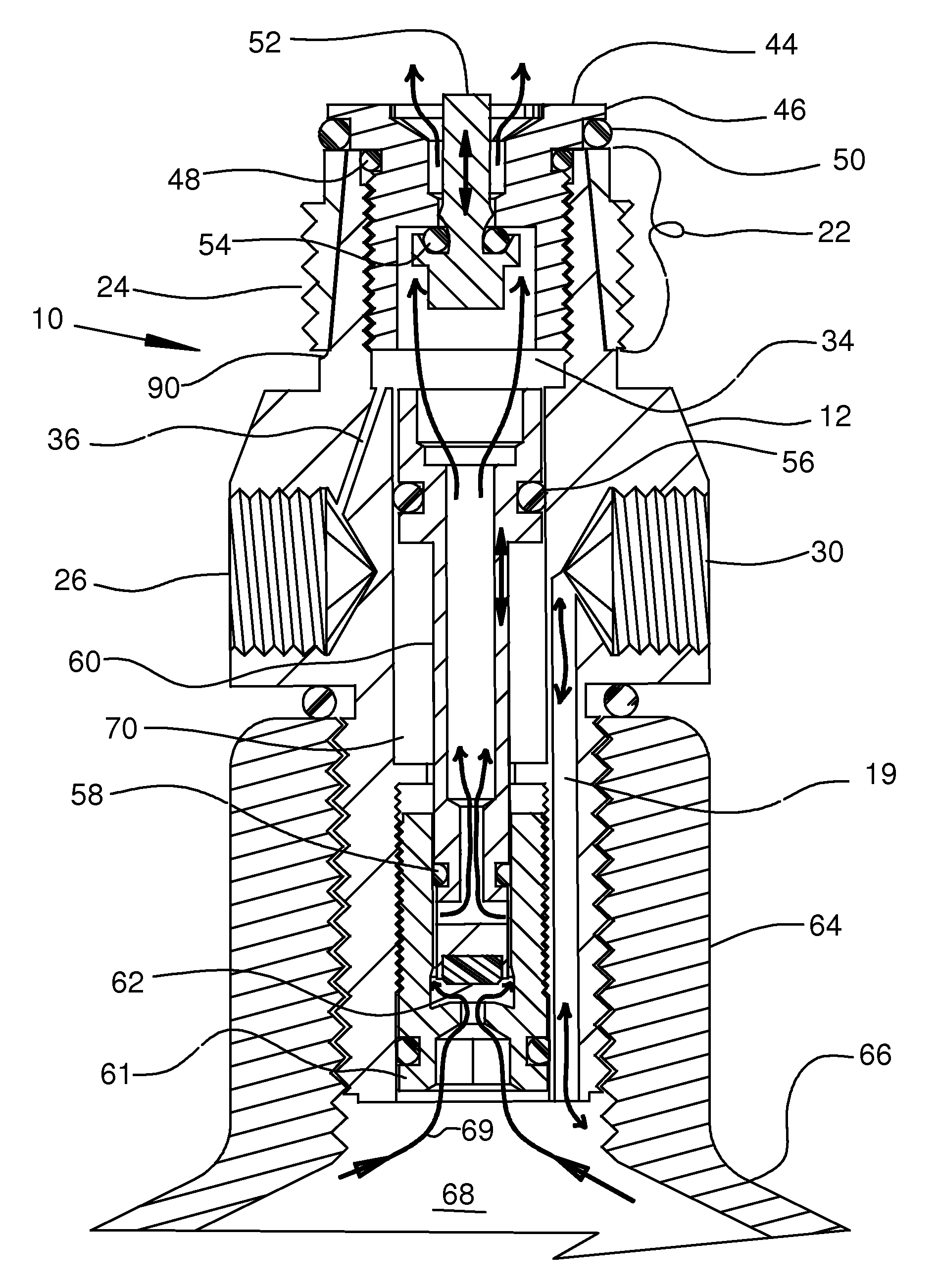
[0017]In embodiments, a regulator is provided that provides improvements in safety, reliability, and functionality. Some embodiments provide improved functionality, particularly when the pressure within the canister is below the pressure at which the regulator is set to deliver gas charges to an attached device. Certain embodiments provide flexibility in accommodating or adapting various components for improved functionality and wider usage of common components. In some embodiments, improvements are achieved by reducing the number and complexity of the housing and operating components, which improves reliability and reduces cost. In some embodiments, fewer machining operations are required to manufacture the housing, thus reducing costs and improving quality.
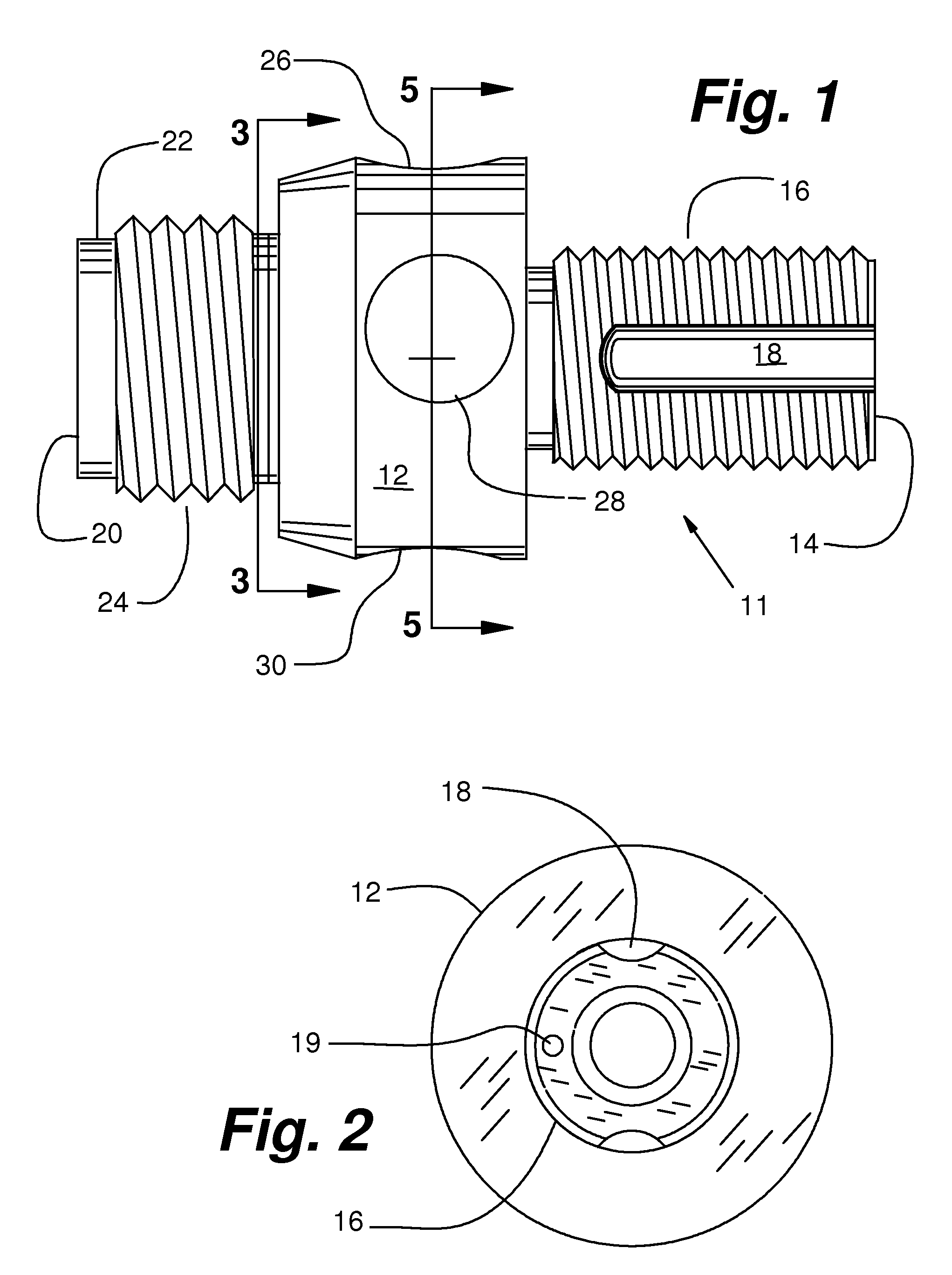
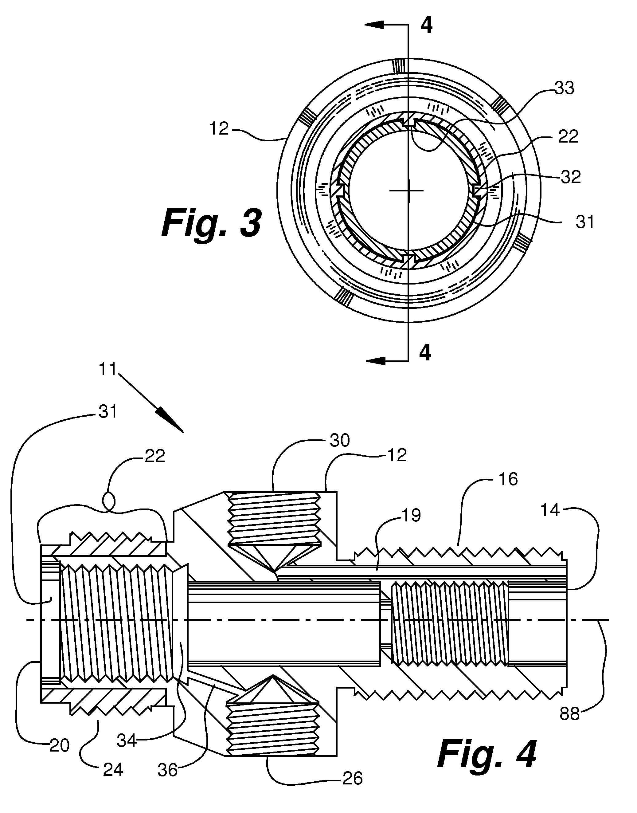
[0030]Similarly, according to certain embodiments comprising stud-socket sets, one or more studs are located on either a sleeve member or a shoulder portion of the body of the regulator. The studs are adapted to non-rotatably engage with mating sockets in the shoulder portion or the sleeve member. In certain embodiments comprising stud-socket sets, 3 studs and mating sockets are sufficient to allow the regulator and tank to be rotated during assembly to bring a pressure gauge for the tank into the operator's view. From 2 to 4 mating stud-socket sets are sufficient for most uses, although from 1 to 5 or 6 or more such stud-socket sets may be employed, if desired. Where no rotatable positioning of the components of the system relative to one another is desired, 1 such stud-socket set may be sufficient. In certain embodiments comprising stud-socket sets, the studs and mating sockets are arrayed generally symmetrically around the longitudinal axis of the shoulder portion of the body. Thus, each sleeve member can be installed so that any stud is received in any mating socket. Alternatively, certain other embodiments may include a greater number of mating sockets than studs, thereby allowing a sleeve comprising fewer studs to engage the selected mating sockets that allow elements of the system, for example, the pressure gauge port, to be positioned during assembly of the system as may be desired. Alternative embodiments may achieve this advantage by providing a single polygonal boss-socket engagement between the sleeve member and the regulator body.
[0031]In addition, according to certain embodiments enabling a frictional engagement between a sleeve member and the body of the regulator, the inner engagement surface of the sleeve member is adapted to non-rotatably engage the outer engagement surface of the distal portion of the body. As with other embodiments, this allows the regulator and tank to be rotated during assembly to bring a pressure gauge for the tank into the operator's view. However, an embodiment allowing frictional engagement offers the further advantage of enabling non-rotational engagement to occur in an infinite number of rotational positions.
[0033]In embodiments, a discharge side seal member is removably mounted in the distal portion of the body. According to certain embodiments, the discharge side seal member is adapted to releasably restrain the sleeve member from sliding axially of the distal portion. Such restrain is accomplished, for example, by providing the discharge side seal member with a flange that is adapted to extend generally radially over a distal end of the sleeve member to releasably restrain the sleeve member from sliding axially of the distal portion of the body. The radial extent of the flange is such that it does not interfere with the threadable engagement of the sleeve with an associated appliance or other system element.
[0036]Typically, the low side pressure relief port is exposed to the level of pressure that exists within the pressure chamber in the body of the regulator. The purpose of the low pressure relief port is to prevent over-pressurization of the pressure chamber with its attendant risk of exploding the regulator and / or the apparatus that is attached to the regulator. The low pressure side relief port is adapted to opening to relieve pressure in the pressure chamber responsive to a level of pressure in the pressure chamber that exceeds a predetermined amount of pressure. The predetermined amount of pressure in the pressure chamber is typically several hundred pounds per square inch below the maximum safe pressure level for the pressure chamber and associated apparatus. In certain embodiments an extra measure of safety is provided by enabling a second low pressure side relief member in the form, for example, of seals for the pressure chamber that release to allow gas to vent from the pressure chamber at approximately the same pressure that activates the opening of the low pressure side relief port.
[0043]In some embodiments of the regulator wherein excess pressure within the pressure chamber is relieved by blowing past the seals of the pressure chamber to atmospheric pressure, the provision of a low pressure side relief port provides a further measure of safety.

Problems solved by technology

Safety is a serious concern with any system where pressurized gas is confined or handled in the equipment.
Often such associated applications are not capable of withstanding the gas pressure that is in the tanks.
This makes the regulator heavier and larger than desired in many systems.
The overall marker-regulator-tank and any associated adaptor system in a paintball gun application is awkward and heavy to handle and carry when the components are large and heavy.
Where a regulator is threadably mounted to an appliance, including adaptors and other devices, fully tightening the threaded connection may cause the regulator to rotate so that the pressure gauge is out of the operator's view.
This supply is depleted after a certain number of cycles.
Typically, the players have no means of replenishing this supply of compressed gas without returning to some central station removed from the playing field.
There are safety concerns with devices that operate on compressed gas.

Method used


Image

  • Compressed Gas Regulator Apparatus
  • Compressed Gas Regulator Apparatus
  • Compressed Gas Regulator Apparatus

Examples


Embodiment Construction

[0085]The following description of preferred embodiments generally relates to regulators for regulating the delivery of discrete charges of gas at predetermined pressures in systems that utilize such pressure regulated gas charges. Certain embodiments of the present invention comprise regulators for compressed gas that exhibit rotational adjustability during assembly. In some embodiments, for added safety, one or two pressure relief members are provided on the low pressure side of the regulator. Certain embodiments of the regulator are adapted to being attached to a marker or paintball gun (not shown) to regulate the flow of compressed gas to the marker. The same or similar elements that appear in different Figs. have been assigned the same reference numbers for purpose of ease of understanding.

[0086]Referring particularly to the Figs. in the accompanying drawings for the purposes of illustration of the best mode only, and not limitation, there is illustrated generally at 10 (see, f...


PUM


Abstract

Regulators for regulating gas that is delivered in discrete charges from a tank that contains compressed gas to a paintball gun, marker, or other application that utilizes or is activated by pressure controlled discrete charges of gas. The regulator has holding, discharge, and fill configurations, controlled by the movement of a piston member in a pressurized chamber, and the activation of a poppet valve on the discharge of the system. One or two low side pressure relief members are provided to prevent the over-pressurization of the pressurized chamber. An externally threaded sleeve member is non-rotatably, but axially slidably received on a distal portion of the body of the regulator so that the sleeve member and distal portion may be axially slidably disengaged, and the regulator can be rotationally positioned so that the pressure gauge is easily viewed by an operator.

Description

RELATED APPLICATIONS[0001]This application claims the benefit of U.S. Provisional Application No. 61 / 144,835 filed Jan. 15, 2009 and U.S. Provisional Application No. 61 / 215,766 filed May 8, 2009, the content of each of which is incorporated by this reference in its entirety for all purposes as if fully set forth herein.TECHNICAL FIELD OF THE INVENTION[0002]The present invention relates generally to regulators for regulating gas that is delivered in discrete charges from a tank that contains compressed gas to a paintball gun, marker, or other application that utilizes or is activated by pressure controlled discrete charges of gas.BACKGROUND OF THE INVENTION[0003]Regulators that deliver discrete charges of pressure controlled gas are employed in a wide variety of industries where discrete charges of pressurized gas are used to, for example, activate controls, provide control, propel projectiles, provide feedstock, diluent, catalyst, carrier, or fuel to processes, or the like. These in...

Claims


Application Information

Patent Timeline
IPC IPC(8): G05D16/10
CPCG05D16/103F41B11/723Y10T137/7793Y10T137/7826
Inventor NEWMAN, SHMUEL DOVIDBROWN, JEFF
Owner LEHR IP LLC
Learn More