Electric heating film and method of producing the same

a technology of electric heating film and heating element, which is applied in the direction of ohmic-resistance heating, ohmic-resistance heating details, electrical equipment, etc., can solve the problems of downward conductive heat loss, restrictions of insulation and vapor barrier, and uncomfortable stratification of air in the room, so as to simplify the production process and eliminate the ever-present hot and cold spots. , the effect of improving the reliability of the production process

Inactive Publication Date: 2010-07-15
LEE DAVID +1
View PDF16 Cites 34 Cited by
  • Summary
  • Abstract
  • Description
  • Claims
  • Application Information

AI Technical Summary

Benefits of technology

[0008]The electric heating film is then mechanically reduced to vary the electrical resistance across the electric heating film. The mechanical reduction includes providing a plurality of perforations across the second polymeric protective film layer, thereby decreasing the surface area of the metalized surface and thus obtaining a specified resistance across the metalized surface.
[0022]It is yet further an objective of the present invention to provide an electric heating film and a method of producing the same which offers a distribution of heat about a drum to prevent the contents thereof from freezing or to maintain at operating temperatures.

Problems solved by technology

Thus the air in the room becomes uncomfortably stratified.
The disadvantages associated with hot water under-floor systems include downward conductive heat loss to the soil or concrete underneath the piping, insulation and vapor barriers restrictions, expansion of joints in concrete and tiled surfaces, crack formation, floor build up due to the height of the piping, expense to install, noise due to bubbling, frequent maintenance, leakage, and water hammer.
However, due to the uneven cable spacing in these resistive circuit patterns, cold and hot spots are common.
The drawbacks associated with the carbon film include unpredictable wattage output.
In addition to the selection of a suitable substrate to be applied to the dielectric material there are drawbacks regarding the application of the substrate to the dielectric material.
Unfortunately, using these techniques yields a resistance which is not very accurate and requires use of propriety methods during the deposition process in order to reduce the variation of resistance across the electric heating film, specifically with a vacuum deposition process.
Unfortunately, these techniques are extremely expensive and time-consuming.
While these prior art devices may be suitable for the particular purpose to which they address, these prior art devices would not be suitable for the purposes of the present invention as heretofore described.

Method used


Image

  • Electric heating film and method of producing the same
  • Electric heating film and method of producing the same
  • Electric heating film and method of producing the same

Examples


Embodiment Construction

[0035]Detailed embodiments of the instant invention are disclosed herein, however, it is to be understood that the disclosed embodiments are merely exemplary of the invention, which may be embodied in various forms. Therefore, specific functional and structural details disclosed herein are not to be interpreted as limiting, but merely as a basis for the claims and as a representation basis for teaching one skilled in the art to variously employ the present invention in virtually any appropriately detailed structure.

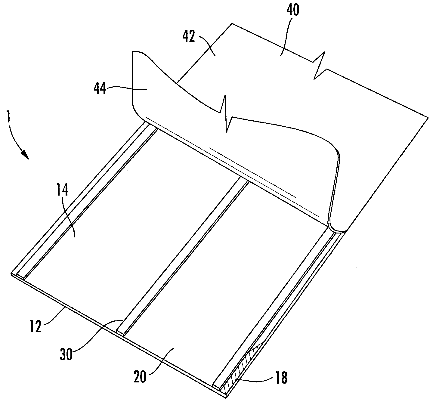
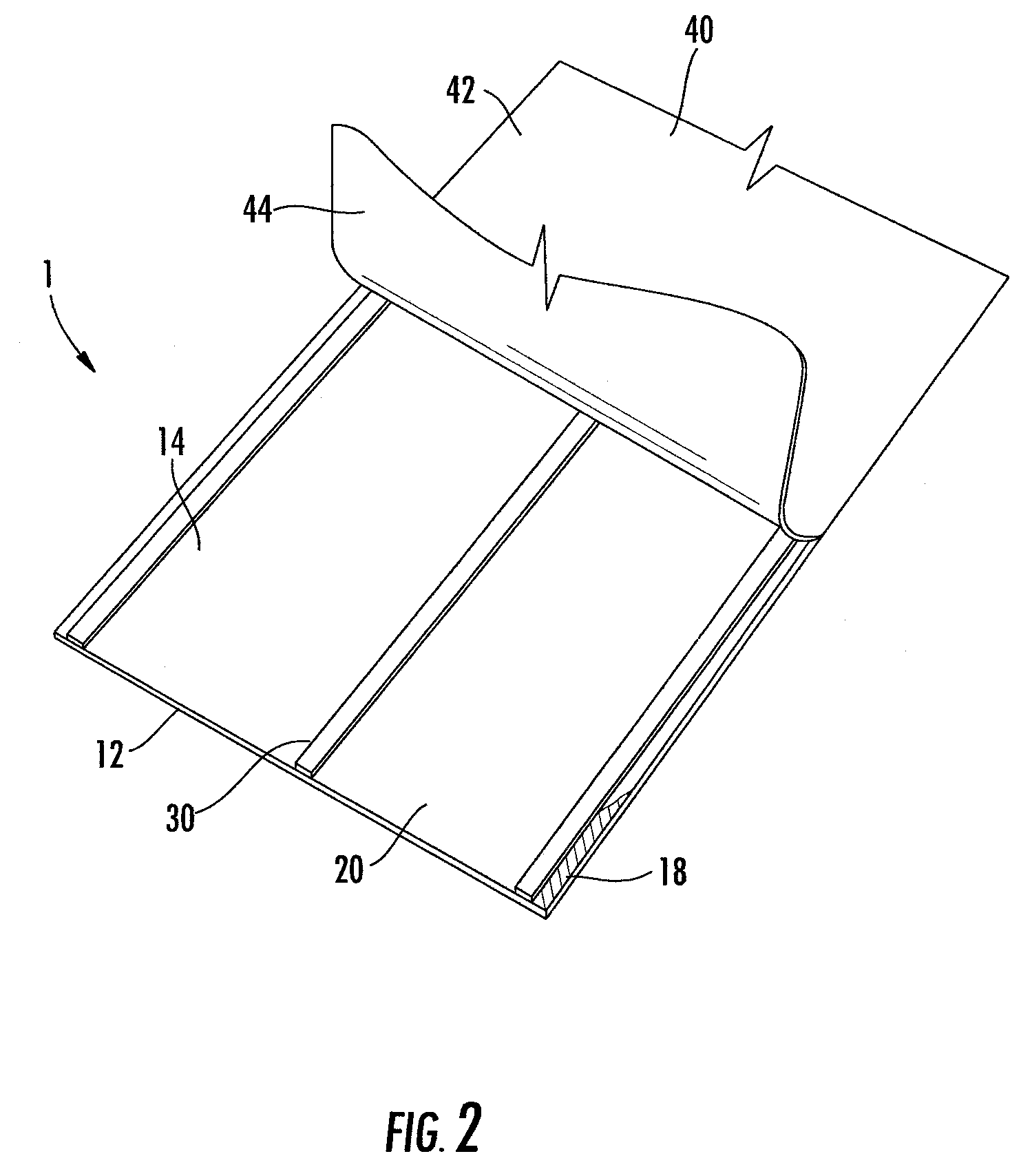
[0036]Referring now to FIGS. 1-8, wherein like components are numbered consistently throughout. FIGS. 1-3 illustrate various embodiment of the electric heating film 1 without mechanical reduction and FIGS. 4-8 illustrate various embodiments of the electric heating film with mechanical reduction. The mechanical reduction method, discussed in further detail below, allows for obtainment of a desired resistance across the electric heating film 1 by formation of perforations a...


PUM

PropertyMeasurementUnit
temperaturesaaaaaaaaaa
thicknessesaaaaaaaaaa
thicknessaaaaaaaaaa

Abstract

An electric heating film comprising of an first polymeric layer having a top surface and bottom surface, a second polymeric layer, a metalized surface, and conductive bus electrodes. The top surface of the first polymeric layer includes a continuous metalized surface of vacuum deposited metal coating and at least one pair of parallel spaced conductive bus electrodes, i.e. copper strips, for connection to a power source. The conductive bus electrodes are conductively adhered to the metalized surface to distribute an electrical current onto the metalized surface to provide a heat across the metalized surface. The second polymeric film sheet layer is provided as a protective layer positioned atop of the top surface of the first polymeric film sheet or enclosing the top and bottom surface of the first polymeric film sheet. The first or the first and the second polymeric layer is mechanical reduced using perforations to reduce the surface area of the metalized surface thereby producing a desired resistance across the metalized surface.

Description

FIELD OF THE INVENTION[0001]This invention relates generally to an electrical heating film and a method for producing the same. The heating film is formed as a continuous vacuum deposited metal coating having a specified resistance which may be modified by virtue of mechanical reduction. The electric heating film is used to distribute heat onto a surface.BACKGROUND OF THE INVENTION[0002]Electric heating films are typically used in applications where space is limited, when a heat output is needed across a surface, where rapid thermal response is desired, or in ultra-clean applications where moisture or other contaminants can migrate. There are various prior art devices which use electric heating film in various applications, for instance the use of electric heating films are disclosed in U.S. Pat. No. 4,990,744 for under-floor heating, U.S. Pat. No. 6,204,480 for window tinting or glazing, U.S. Pat. No. 5,990,449 for mirror deicing or defogging, U.S. Pat. No. 6,686,562 for vehicle he...

Claims


Application Information

Patent Timeline
Patent Type & Authority Applications(United States)
IPC IPC(8): H05B3/34H05B3/02
CPCH05B3/34H05B2203/011H05B2203/013Y10T29/49083H05B2203/022H05B2203/026H05B2203/029H05B2203/017
Inventor LEE, DAVIDSCHALANSKY, CARL
Owner LEE DAVID
Why Eureka
Try Eureka