Method for making composite sputtering targets and the tartets made in accordance with the method

a composite sputtering target and composite technology, applied in the direction of thin material processing, transportation and packaging, etc., can solve the problems of significant material loss in the recycling process, impractical sputtering of the target material further, etc., to reduce the amount of precious metal containing sputtering material, reduce the cost of ownership of the sputtering target assembly, and increase the material efficiency

Inactive Publication Date: 2010-07-15
SCI ENGINEERED MATERIALS INC
View PDF17 Cites 4 Cited by
  • Summary
  • Abstract
  • Description
  • Claims
  • Application Information

AI Technical Summary

Benefits of technology

[0012]In accordance with the invention, there is provided a method of making a sputtering target assembly that confines precious metal containing sputtering target materials to the sputtering area of the target thereby reducing the amount of precious metal containing sputtering material required to produce the sputtering target assembly, and further increases the efficiency of the material dedicated to the sputtering process, and thus reduces the cost of ownership of the sputtering target assembly as well as the capital investment needed for the sputtering process. The method involves providing a backing plate of a relatively inexpensive material, that is chemically and mechanically compatible with the precious metal containing sputtering material, with a depression in the surface, (which can in the first instance be machined into the backing plate) that corresponds to the sputtering erosion pattern observed in used sputtering targets, placing the backing plate into a graphite die shaped to accommodate the geometry (i.e., the size and shape) of the backing plate, filling the depression in the backing plate with a powder of the precious metal containing sputtering material, then placing a graphite ram on top of the powder layer. The die containing the backing plate powder assemblage is then placed in a vacuum hot press to consolidate and densify the precious metal containing sputtering target material powder into the backing plate depression. Not only does vacuum hot pressing consolidate and densify the precious metal containing sputtering target material, the hot pressing also facilitates the formation of a strong inter-metallic bond between the precious metal containing sputtering material and the backing plate material creating a strong mechanical attachment as well as an intimate electrical and thermal conduction path between the precious metal containing sputtering target material and the backing plate. After hot pressing, a minimal amount of machining may be required to obtain the required dimensional specifications for the particular sputtering target design.

Problems solved by technology

Eventually, the erosion groove becomes deep enough that further sputtering of the target material is impractical and at that point the sputtering target is considered “spent”.
It often takes several weeks, or even months to render the remaining material from a spent target available and in addition, there is a significant material loss in the recycling process.
While for most materials used in the sputtering process recycling is economically feasible, this is not necessarily the case for relatively expensive materials such as those that contain precious metals such as Pt, Ru, Pd, Os, Ir, Rh, and Re or combinations of precious metals and other metals or metal oxides.
In this case the cost and the amount of material loss from the recycling processes are substantial enough to warrant a significant change in the way precious metal containing sputtering targets are manufactured.
However, since the process involves HIP'ing powder contained within a metal can, it is relatively costly due to the use of expensive canning materials, machining, canning as well as HIP procedures and equipment which add to manufacturing cost.
However, there still remains a considerable amount of expensive material in use that is not used in the sputtering process leading to a still relatively high cost of ownership.

Method used


Image

  • Method for making composite sputtering targets and the tartets made in accordance with the method
  • Method for making composite sputtering targets and the tartets made in accordance with the method
  • Method for making composite sputtering targets and the tartets made in accordance with the method

Examples


example 1

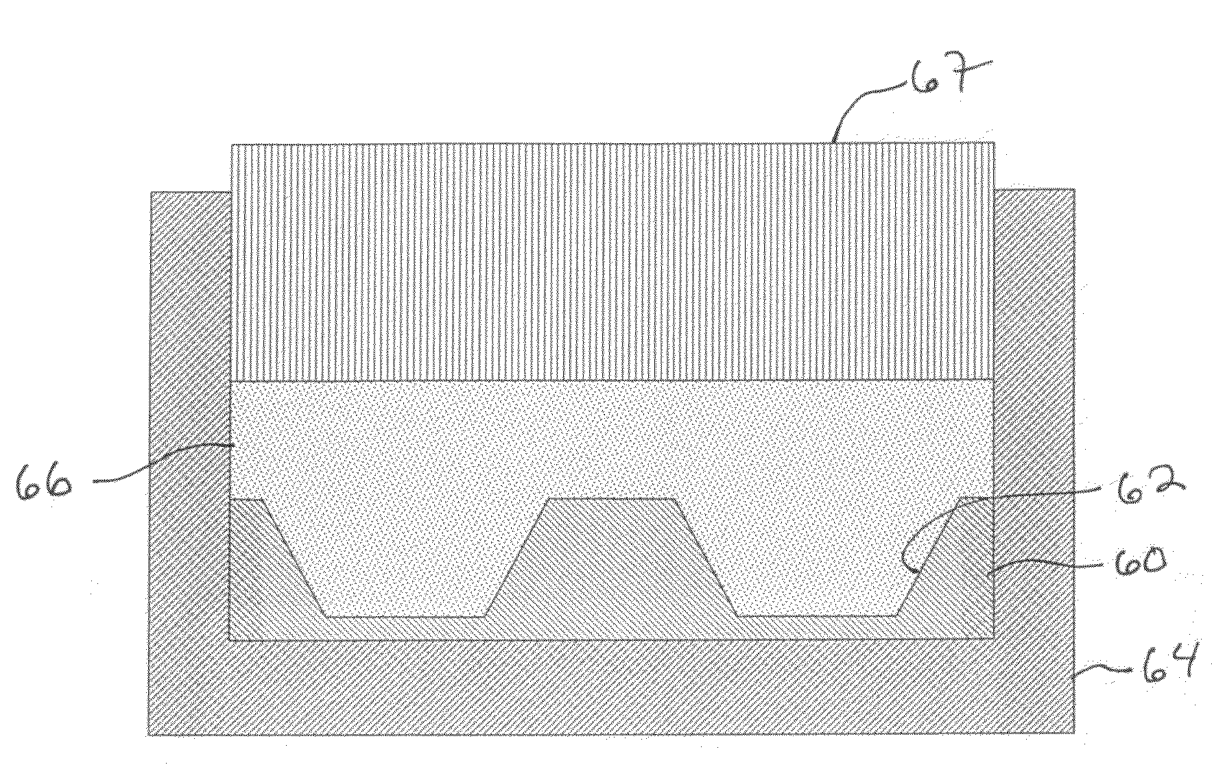
[0031]A 2.03″ diameter by 0.31″ thick circular Ru composite sputtering target was fabricated with a Mo backing plate using the disclosed invention. Using a lathe, a 2.03″ diameter by 0.25″ thick piece of Mo was machined in such a way as to provide a cavity concentric with the diameter of the Mo piece with a depth of 0.115″ deep and top diameter of 1.84″ and a bottom diameter of 1.55″ (forming a frustum shape). The machined Mo piece was placed into a graphite hot press die and 100 grams of Ru powder was poured into the die cavity so as to fill the cavity in the Mo piece and cover the top of it. A graphite die ram was then placed into the die cavity and lowered onto the top of the Ru powder.

[0032]The die assemblage was subsequently placed in a hydraulic press and pressed to a few hundred pounds of load to pre-compress the Ru powder. Then the die assemblage was placed into a vacuum hot press and processed at 1525° C. for 0.5 hours at 500 psi at a vacuum level of 200 mTorr. After hot pr...

example 2

[0036]A 2.03″ diameter by 0.31″ thick circular Ru composite sputtering target was fabricated with an Nb backing plate using the disclosed invention. Using a lathe, a 2.03″ diameter by 0.25″ thick piece of Nb was machined in such a way as to provide a cavity concentric with the diameter of the Nb piece with a depth of 0.115″ deep and top diameter of 1.84″ and a bottom diameter of 1.55″ (forming a frustum shape). The machined Nb piece was placed into a graphite hot press die and 100 grams of Ru powder was poured into the die cavity so as to fill the cavity in the Mo piece and cover the top of it. A graphite die ram was then placed into the die cavity and lowered onto the top of the Ru powder.

[0037]The die assemblage was subsequently placed in a hydraulic press and pressed to a few hundred pounds of load to pre-compress the Ru powder. Then the die assemblage was placed into a vacuum hot press and processed at 1525° C. for 0.5 hours at 500 psi at a vacuum level of 200 mTorr. After hot p...

example 3

[0040]A 2.03″ diameter by 0.31″ thick circular Ru composite sputtering target was fabricated with a Ta backing plate using the disclosed invention. Using a lathe, a 2.03″ diameter by 0.25″ thick piece of Ta was machined in such a way as to provide a cavity concentric with the diameter of the Ta piece with a depth of 0.115″ deep and top diameter of 1.84″ and a bottom diameter of 1.55″ (forming a frustum shape). The machined Ta piece was placed into a graphite hot press die and 100 grams of Ru powder was poured into the die cavity so as to fill the cavity in the Ta piece and cover the top of it. A graphite die ram was then placed into the die cavity and lowered onto the top of the Ru powder.

[0041]The die assemblage was subsequently placed in a hydraulic press and pressed to a few hundred pounds of load to pre-compress the Ru powder. Then the die assemblage was placed into a vacuum hot press and processed at 1525° C. for 0.5 hours at 500 psi at a vacuum level of 200 mTorr. After hot pr...


PUM

PropertyMeasurementUnit
temperatureaaaaaaaaaa
pressureaaaaaaaaaa
temperatureaaaaaaaaaa

Abstract

Composite sputtering targets are made by hot pressing metal or metal containing powders into a backing plate which can be comprised of a different material with a depression formed in a surface or can be a used sputtering target of the same or different material. The depression corresponds to the erosion pattern of a target having the same geometry. The depression can be formed for example, by machining. The backing plate is loaded into a graphite die and covered with the sputtering material to form an assembly. A ram is added and the assembly with the ram is loaded into a hot press which is taken to an appropriate pressure and temperature under vacuum to form a composite sputtering target having a sputtering zone of densified sputtering material.

Description

FIELD OF THE INVENTION[0001]The invention relates to composite sputtering target assemblies made by hot pressing metal or metal containing powders into a metal backing plate. More particularly, the invention relates to a method of making a hot pressed composite sputtering target assembly that reduces the amount of relatively expensive materials such as precious metal containing materials required to prepare the target by confining these materials to the area of the target utilized in the sputtering process. The invention further relates to the target, which is produced by the method.BACKGROUND OF THE INVENTION[0002]Thin layers of many materials may be deposited on a substrate material by a process known as DC-magnetron sputtering. A typical sputtering system includes a means for generating a high energy plasma that removes the material to be deposited from the surface of a source forming a vapor of that material that condenses on the surface of the desired substrate. In such a syste...

Claims


Application Information

Patent Timeline
Patent Type & Authority Applications(United States)
IPC IPC(8): B22F3/14
CPCB22F3/14B22F7/08B22F2003/247B22F2998/10B22F2999/00Y10T428/12049B22F3/24B22F2201/20
Inventor CAMPBELL, SCOTT
Owner SCI ENGINEERED MATERIALS INC
Why Eureka
Try Eureka