Device control device and device control method

a technology of device control and control device, which is applied in the direction of instruments, angiography, applications, etc., can solve the problems of need to discriminate, no established technique for evaluating the health condition of a person, and no established technique for back calculation, so as to improve the health condition of users

Inactive Publication Date: 2010-07-15
PANASONIC CORP
View PDF5 Cites 6 Cited by
  • Summary
  • Abstract
  • Description
  • Claims
  • Application Information

AI Technical Summary

Benefits of technology

[0034]The present invention provides a device control device that evaluates a user's health condition based on a vital sign such as a pulse wave and controls a device, more specifically, the device control device discriminates the influence of a thermal environment and the influence of a health condition by firstly determining whether or not a change in the vital sign is made due to the influence of the thermal environment, and performs reliable device control for making better the user's health condition.

Problems solved by technology

However, such correlation analysis was performed based on changes in vital signs observed in segments where the health conditions surely changed, and thus these results are mere results obtained at laboratories far different from real environments.
At present, there is no established technique for performing back calculation to evaluate the health condition of a person in the case where a change in a vital sign is observed.
However, pulse waves are susceptible to body movements or the like, and thus there is a need to discriminate between pulse wave signs and noise.

Method used


Image

  • Device control device and device control method
  • Device control device and device control method
  • Device control device and device control method

Examples


embodiment 1

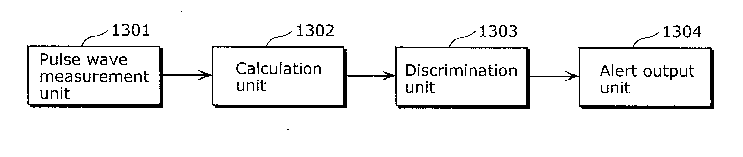
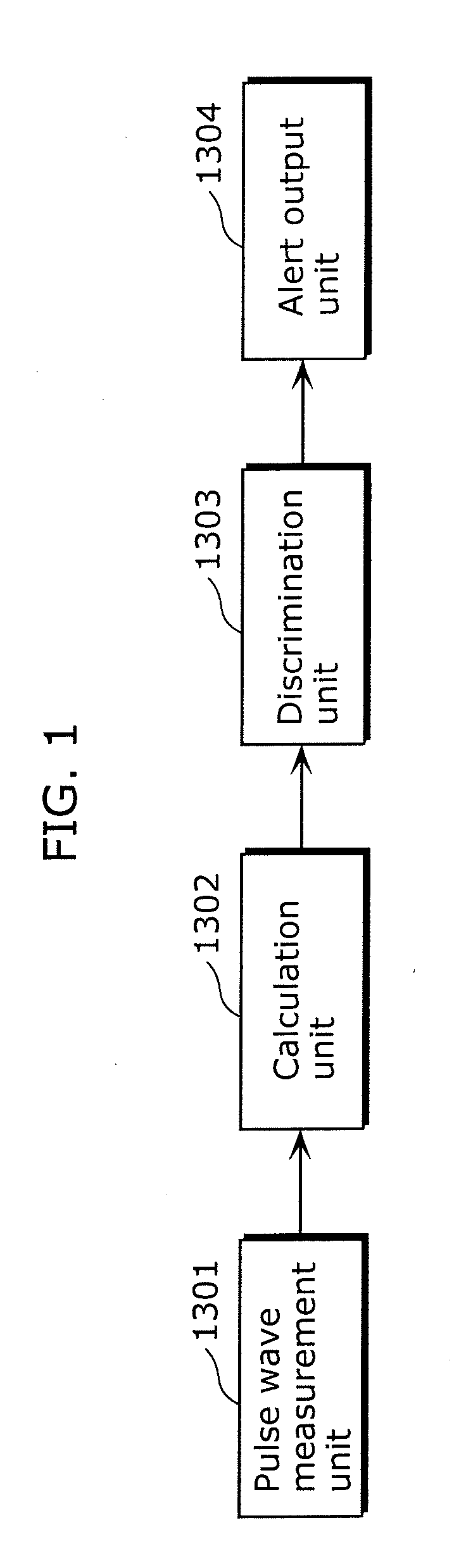
[0108]FIG. 7 is a block diagram showing the structure of a device control device according to Embodiment 1 of the present invention. The device control device shown in FIG. 7 is configured with known computers for example, and includes a vital sign measurement unit 101, a parameter extraction unit 102, a determination unit 120, and a control unit 130. These processing units function when the program is executed by a CPU of a computer storing an installed device control program designed according to this embodiment.

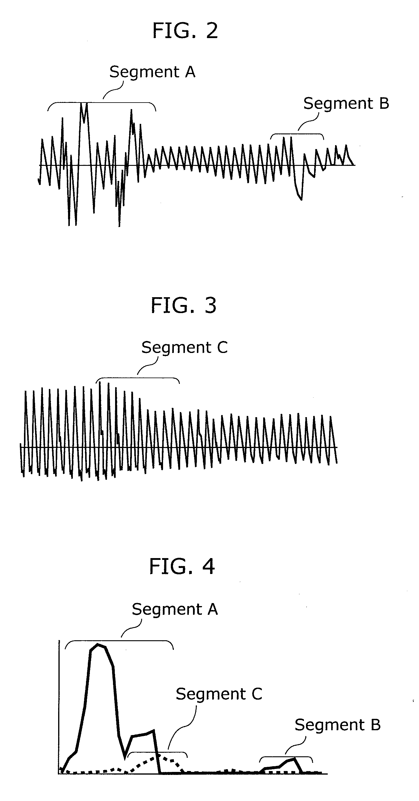
[0109]The vital sign measurement unit 101 samples a user's finger-tip pulse wave detected by a known transducer or the like at a predetermined sampling cycle, and obtains pulse wave data in time series. The parameter extraction unit 102 extracts the amplitude of the pulse waveform from the pulse wave data as parameter values for evaluating the pulse wave, and accumulates the parameter values.

[0110]The determination unit 120 is a processing unit for determining the factor o...

embodiment 2

[0172]The following description is given of a device control device according to Embodiment 2 of the present invention. The same elements as those of the device control device according to Embodiment 1 are assigned with the same numerical references. The functions and names are also the same, and thus no detailed descriptions are repeated here.

[0173]FIG. 23 is a block diagram showing the structure of a device control device according to Embodiment 2 of the present invention. The device control device shown in FIG. 23 is configured with known computers for example, and includes a vital sign measurement unit 101, a parameter extraction unit 102, a determination unit 520, and a control unit 130. These processing units function when the program is executed by a CPU of a computer storing an installed device control program designed according to this embodiment.

[0174]The determination unit 520 is a processing unit for determining the factor of a change in the pulse wave data using paramet...

embodiment 3

[0190]The following description is given of a device control device according to Embodiment 3 of the present invention. The same elements as those of the device control device according to Embodiment 1 are assigned with the same numerical references. The functions and names are also the same, and thus no detailed descriptions are repeated here.

[0191]FIG. 28 is a block diagram showing the structure of a device control device according to Embodiment 3 of the present invention. The device control device shown in FIG. 28 is configured with known computers for example, and includes a vital sign measurement unit 101, a parameter extraction unit 102, a determination unit 920, and a control unit 130. These processing units function when the program is executed by a CPU of a computer storing an installed device control program designed according to this embodiment.

[0192]The determination unit 920 is a processing unit for determining the factor of a change in the pulse wave data using paramet...


PUM

PropertyMeasurementUnit
frequencyaaaaaaaaaa
frequencyaaaaaaaaaa
temperatureaaaaaaaaaa

Abstract

A device control device for controlling an on-vehicle device based on a vital sign of a user, the device control device including: a vital sign measurement unit (101) configured to measure, in time series, the vital sign of the user; a parameter extraction unit (102) configured to extract time-series parameter values for evaluating current statuses of the user based on the vital sign measured continuously by the vital sign measurement unit (101); a determination unit (120) configured to determine whether a factor of a change in the vital sign is a change in a health condition of the user or a change in an environment temperature around the user, based on the parameter values extracted by the parameter extraction unit; and a control unit (130) configured to control the on-vehicle device based on a result of the determination made by the determination unit (120).

Description

TECHNICAL FIELD[0001]The present invention relates to device control devices for controlling on-vehicle devices, and in particular to a device control device for evaluating the health condition of a person based on a change in a vital sign, and performing device control suitable for the evaluated health condition in order to make better the person's health condition.BACKGROUND ART[0002]Recently, various research groups have been studying techniques for evaluating the health conditions of people based on their vital signs. As the results, some researchers found the correlation between the health conditions of the people and their vital signs, and proposed methods for evaluating the health conditions of people based on their vital signs at academic meetings. However, such correlation analysis was performed based on changes in vital signs observed in segments where the health conditions surely changed, and thus these results are mere results obtained at laboratories far different from ...

Claims


Application Information

Patent Timeline
Patent Type & Authority Applications(United States)
IPC IPC(8): A61B5/024A61B5/00G01K1/00
CPCA61B5/0245A61B5/18A61B5/7207A61B5/7239A61B2560/0252A61B5/7296A61B5/02116
Inventor KANAI, ETSUKOFUNAKURA, MASAMIMAEDA, YASUTAKANODA, MAKIKO
Owner PANASONIC CORP
Why Eureka
Try Eureka