Medical Lead Termination Sleeve for Implantable Medical Devices

a technology of medical devices and lead termination sleeves, which is applied in the field of medical lead termination sleeves for implantable medical devices, can solve the problems of poor quality welds, manufacturing challenges, and sustained galvanic corrosion, and achieve the effect of robust electrical connections

Active Publication Date: 2010-07-15
CYBERONICS INC
View PDF103 Cites 32 Cited by
  • Summary
  • Abstract
  • Description
  • Claims
  • Application Information

AI Technical Summary

Benefits of technology

[0008]A termination sleeve is provided that is crimped onto a distal end of an electrical lead wire, so that the termination sleeve can then be welded to an electrode. Other embodiments are directed to an electrical lead wire and electrode in a combination suitable for use with implanted medical devices, and to a method for coupling an electrical lead wire and electrode to achieve a robust electrical connection suitable for use with such medical devices. An exemplary electrical lead wire is optimized for strength, and exemplary electrodes and termination sleeves are optimized for biocompatibility and corrosion resistance—in accord with this novel approach.

Problems solved by technology

However, there are several disadvantages to this technique: (1) lead wire and electrode materials are often dissimilar and are at risk of sustaining galvanic corrosion when used together in an in vivo environment in which they are exposed to bodily fluids; (2) if lead wire and electrode materials are dissimilar, welds between such dissimilar materials are typically of lower quality than welds between similar materials; (3) lead wire diameters for implanted medical devices are generally small, so that properly welding these small-diameter lead wires to electrodes can present manufacturing challenges; and (4) laser spot welding of such relatively small diameter lead wires can lead to poor quality welds.
Accordingly, a desirable material for a lead wire might not be desirable for an electrode.
Where two different metals are connected together and exposed to a common electrolyte (in the case of an implanted medical device, bodily fluid represents the common electrolyte), there exists a risk of galvanic corrosion, which is highly undesirable in the context of the long term reliability of an implantable medical device.
Aligning such small diameter lead wires for welding on a relatively larger electrode can be challenging, especially with regards to multifilar wires having eight or more individual wire strands.
In the case of a relatively small diameter lead wire, the lead wire will melt well before the electrode (because the electrode is more massive than the lead wire), and the lead wire can either melt entirely (leading to immediate failure of the weld), or the diameter of the lead wire can be greatly reduced when melted, generating a weak spot that is prone to failure.
A further problem is that where the lead wire material has been initially heat treated, the heat from the welding operation can adversely affect the initial heat treatment, reducing the strength of the lead wire.

Method used


Image

  • Medical Lead Termination Sleeve for Implantable Medical Devices
  • Medical Lead Termination Sleeve for Implantable Medical Devices
  • Medical Lead Termination Sleeve for Implantable Medical Devices

Examples


first exemplary embodiment

of Termination Sleeve

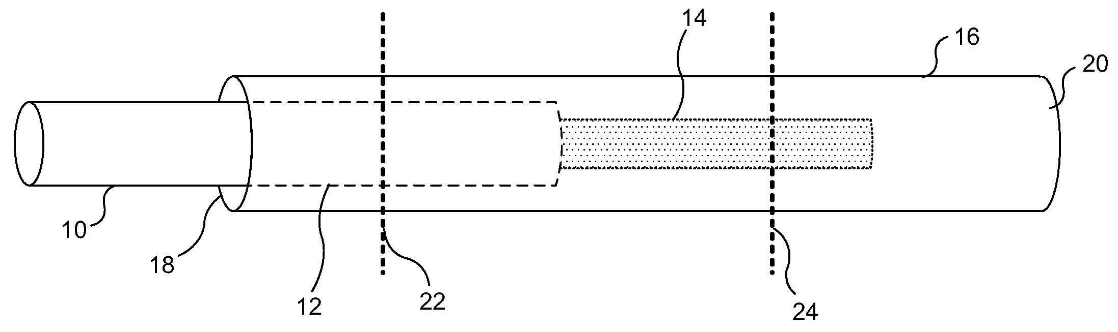
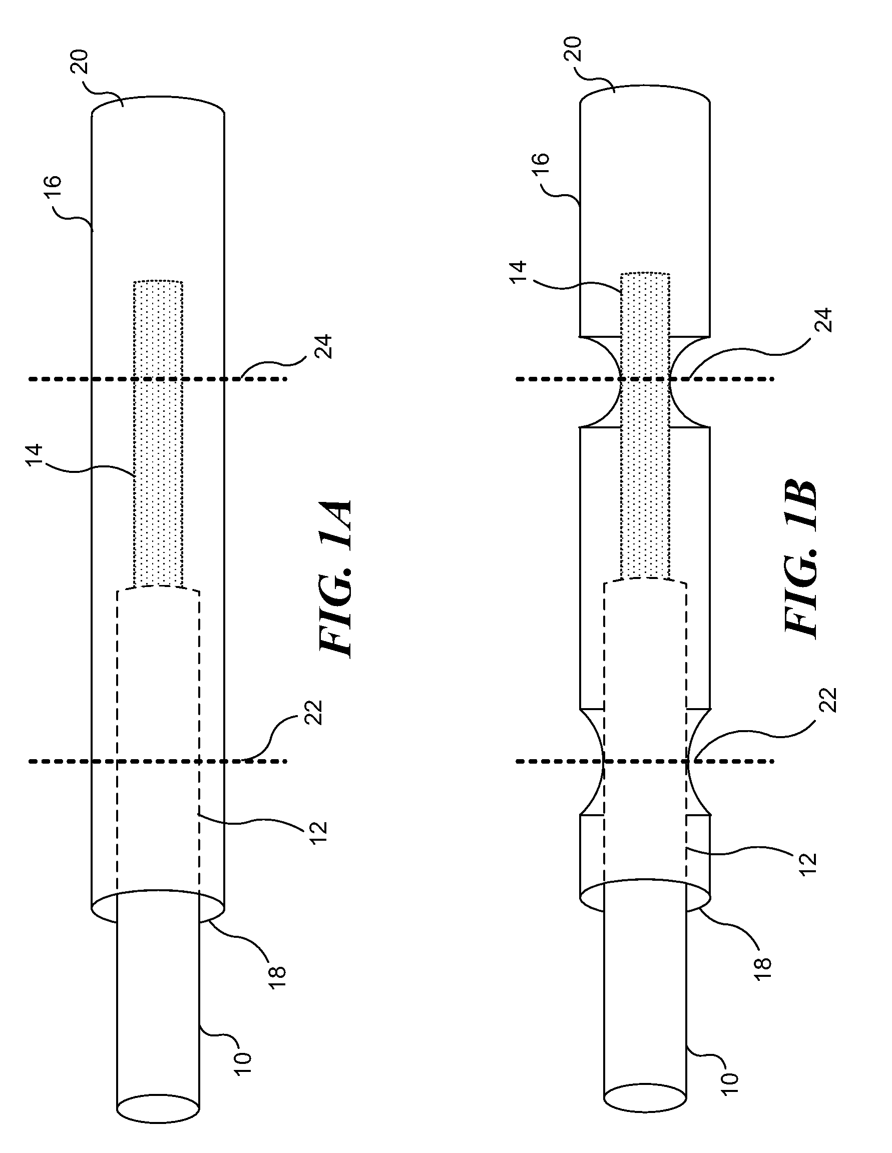
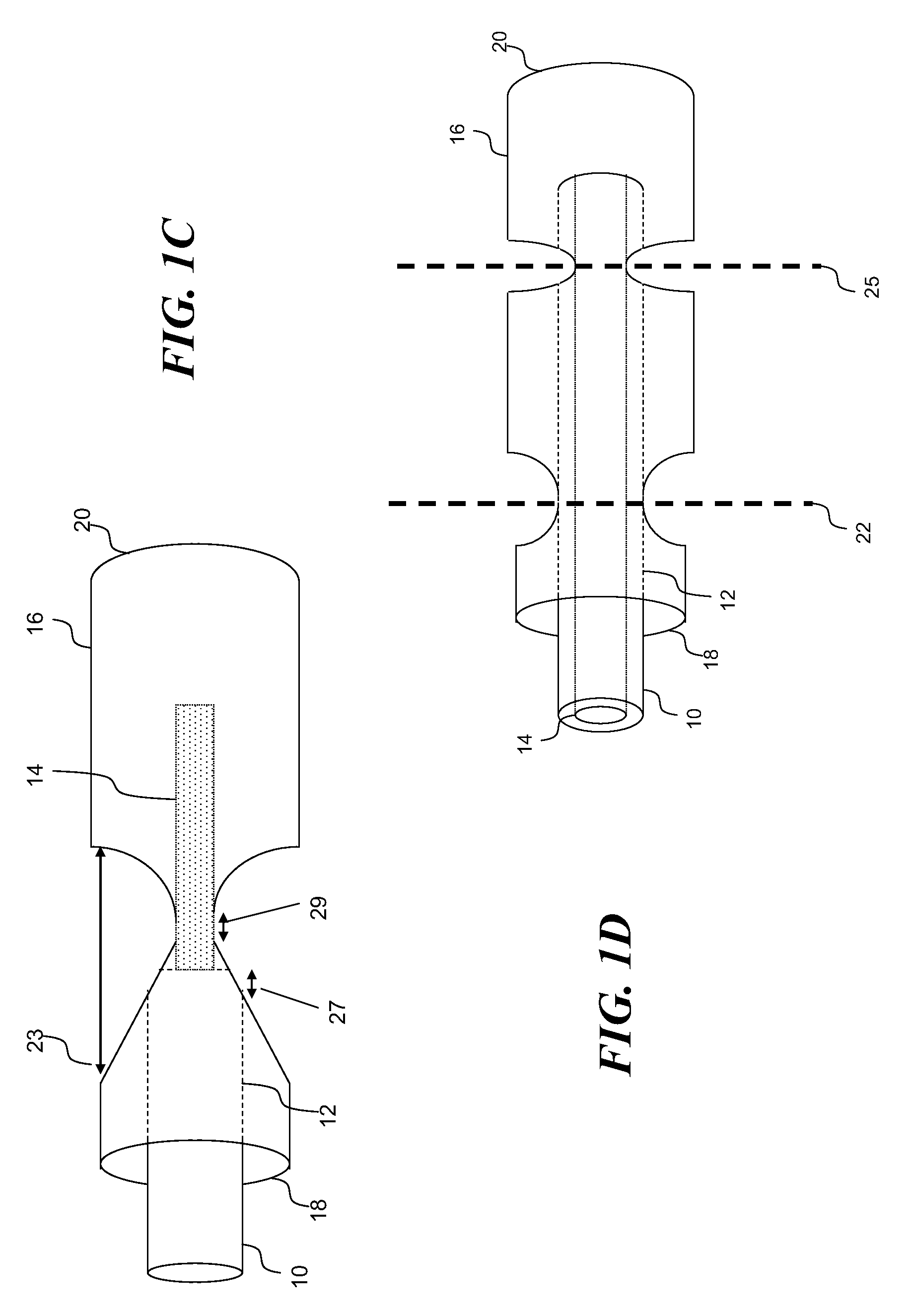
[0036]FIG. 1A illustrates a lead wire inserted into an exemplary termination sleeve for use with implantable medical devices, wherein the termination sleeve includes an open proximal end and a closed distal end, relative to the medical lead wire. FIG. 1B illustrates the medical lead wire and termination sleeve combination of FIG. 1A, after the termination sleeve has been modified to engage the medical lead wire at a first location and a second location, the termination sleeve sealingly engaging an insulating protective cover of the medical lead wire at the first location, and conductively engaging the medical lead wire at the second location, fastening the medical lead wire within the termination sleeve and making an electrical connection between the two components. The termination sleeve can next be electrically and physically coupled to an electrode, as shown in FIG. 2. Significantly, the relatively larger termination sleeve is easier to manipulate than the re...


PUM

PropertyMeasurementUnit
diameteraaaaaaaaaa
diameteraaaaaaaaaa
diameteraaaaaaaaaa

Abstract

A wire and electrode combination suitable for use with implanted medical devices, and a method for coupling the wire and electrode to achieve a robust electrical connection suitable for use with such medical devices are disclosed. The apparatus employs a wire that is optimized for strength, an electrode optimized for biocompatibility, and a termination sleeve with a closed distal end for coupling the wire to the electrode, while eliminating the potential for galvanic corrosion, enhancing weld quality, and facilitating manufacture of the apparatus. The method involves compressing the sleeve to engage the wire at two locations, where contact between the sleeve and wire at the first location seals the interior of the sleeve, and contact between the sleeve and wire at the second location electrically couples the wire to the sleeve. The sleeve, which is easier to manipulate than the wire, is then spot welded to the electrode.

Description

CROSS-REFERENCE TO RELATED APPLICATIONS[0001]This application claims the benefit of U.S. Provisional Application No. 61 / 143,571, filed Jan. 9, 2009, which is incorporated herein by reference in its entirety.BACKGROUND OF THE INVENTION[0002]Implantable medical devices often include an electrode to which a conductive wire is attached. Conventionally, medical lead wires are simply welded to an electrode. However, there are several disadvantages to this technique: (1) lead wire and electrode materials are often dissimilar and are at risk of sustaining galvanic corrosion when used together in an in vivo environment in which they are exposed to bodily fluids; (2) if lead wire and electrode materials are dissimilar, welds between such dissimilar materials are typically of lower quality than welds between similar materials; (3) lead wire diameters for implanted medical devices are generally small, so that properly welding these small-diameter lead wires to electrodes can present manufacturi...

Claims


Application Information

Patent Timeline
Patent Type & Authority Applications(United States)
IPC IPC(8): A61N1/05A61B5/04
CPCA61B5/04H01R4/20Y10T29/49218H01R2201/12A61N1/05A61B5/4094A61B5/24
Inventor FLOYD, JAREDGENAU, CHRISTOPHERLEYDE, KENT W.
Owner CYBERONICS INC
Why Eureka
Try Eureka