

Vascular Graft With Kink Resistance After Clamping
- Summary
- Abstract
- Description
- Claims
- Application Information
AI Technical Summary
Benefits of technology
Problems solved by technology
Method used
Image

Examples
Embodiment Construction
in conjunction with the accompanying drawings that are first briefly described.
BRIEF DESCRIPTION OF THE DRAWINGS
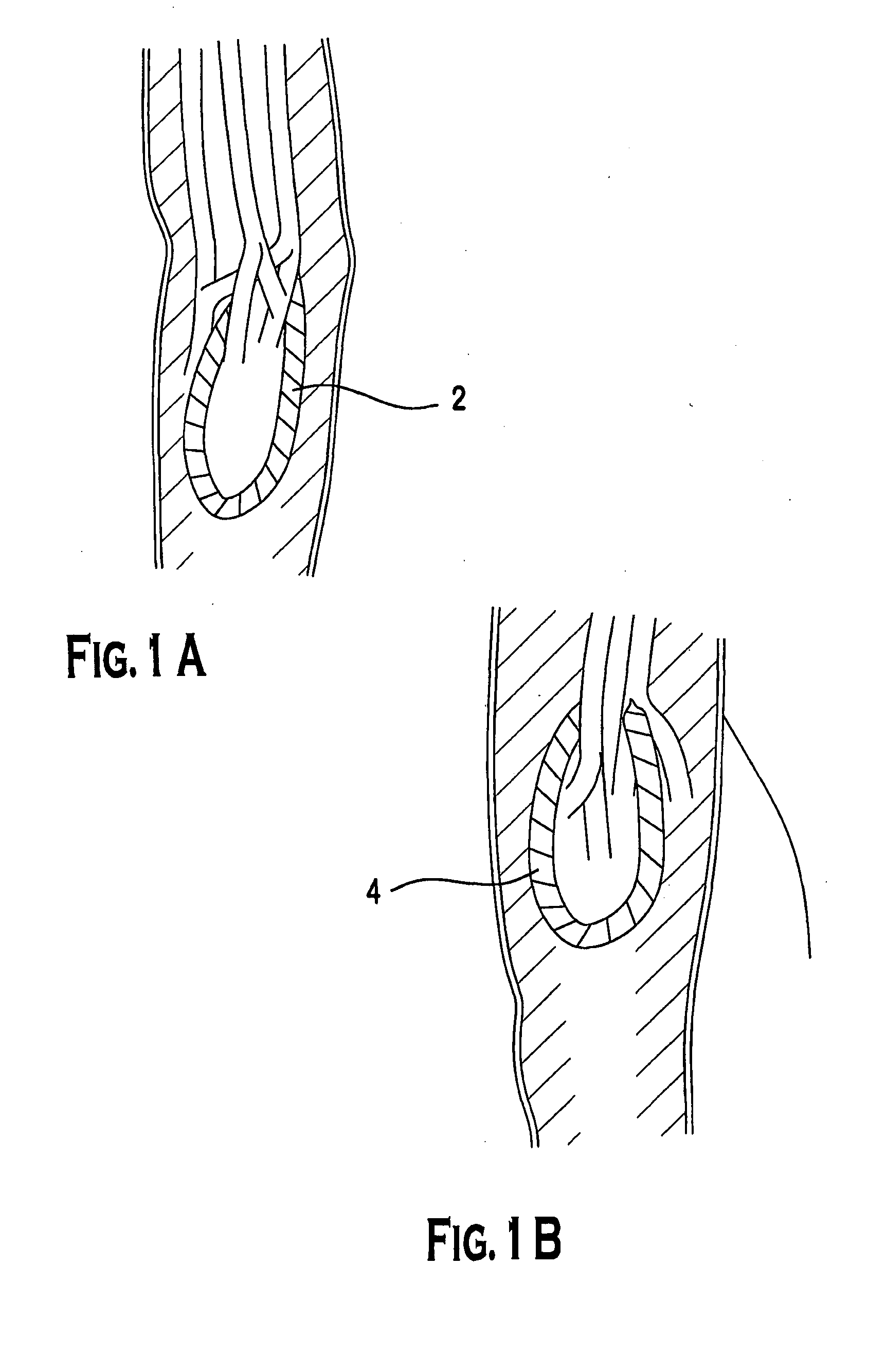
[0019]FIG. 1A is a depiction of loop AV graft implanted in the forearm of a patient.
[0020]FIG. 1B is a depiction of loop AV graft implanted in the thigh of a patient.
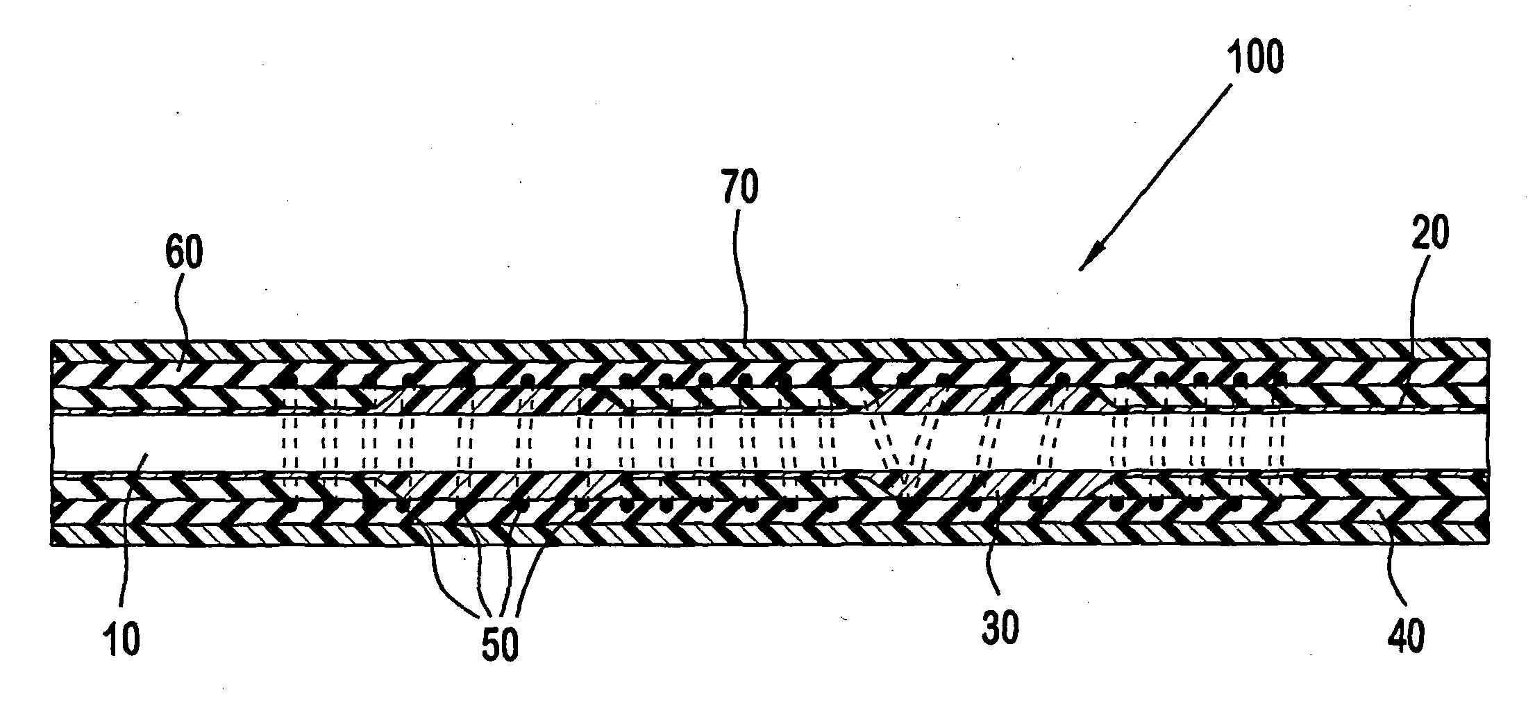
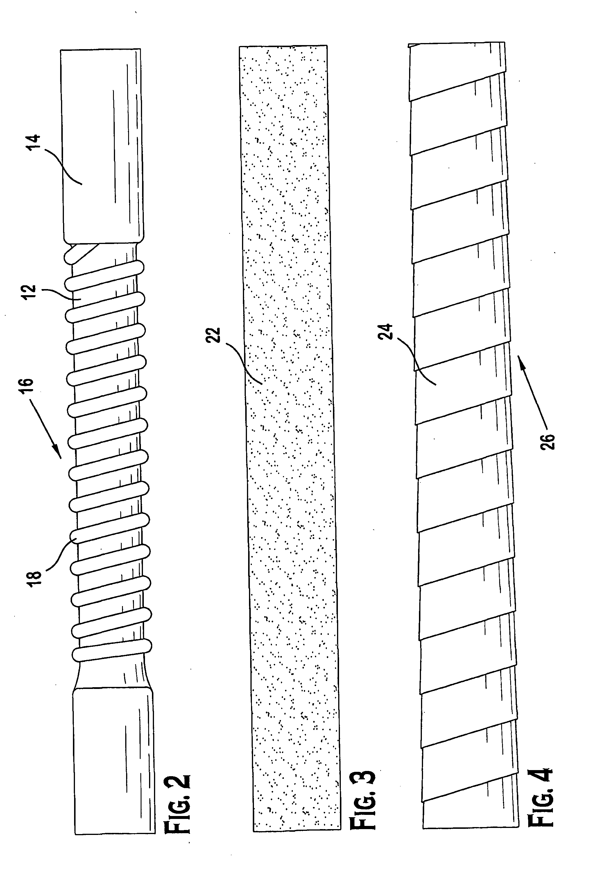
[0021]FIG. 2 is an illustration of an ePTFE graft having an ePTFE substrate with a sealant layer on either side of a middle portion, which has beading spiraled therearound.
[0022]FIG. 3 is an illustration of the graft of FIG. 2 with a foam layer disposed over the sealant layer and beading.
[0023]FIG. 4 is an illustration of the graft of FIG. 3 with an ePTFE tape wrapped around the foam layer.
[0024]FIG. 5 is an illustration of the graft of FIG. 4 shown in a bent configuration.
[0025]FIG. 6 is an illustration of an ePTFE graft having an ePTFE substrate with a sealant layer over its length, the sealant layer having grooved sections cut in spaced apart intervals therein.
[0026]FIG. 7 is an illustration of the graft of...
PUM
| Property | Measurement | Unit |
|---|---|---|
| Length | aaaaa | aaaaa |
| Length | aaaaa | aaaaa |
| Fraction | aaaaa | aaaaa |
Abstract
Description
Claims
Application Information