
Vehicle load weight detecting apparatus

Active Publication Date: 2010-07-22
PACIFIC INDUSTRIAL CO LTD
View PDF2 Cites 32 Cited by
  • Summary
  • Abstract
  • Description
  • Claims
  • Application Information

AI Technical Summary

Benefits of technology

[0007]Accordingly, it is an objective of the present invention to provide a vehicle load weight detecting apparatus that accurately detects the weight of a load carried by the vehicle with a simplified structure and less costs.

Problems solved by technology

However, since the internal air pressure of the tires changes only slightly with respect to changes in the load applied to the tires, it is realistically difficult to accurately compute the total weight of the vehicle and the weight of the load carried by the vehicle from the relationship between the internal air pressure of the tire and the load applied to the tire.
Thus, the apparatus of Japanese Patent No. 3578311 is not practical.
Thus, the configuration of the apparatus is complicated and the costs are increased.
In addition, in the case in which the load sensor is provided between the rim of each wheel and the associated tire, air is more likely to leak from between the rim and the tire.
Moreover, the operation for mounting the tires on the wheels becomes very cumbersome.
Furthermore, in particular, when the vehicle is travelling, since sudden and great dynamic load is applied to the load sensors, it is not preferable to use the load sensors under such harsh conditions in the aspect of durability.

Method used


Image

  • Vehicle load weight detecting apparatus
  • Vehicle load weight detecting apparatus
  • Vehicle load weight detecting apparatus

Examples


Embodiment Construction

[0021]One embodiment of the present invention will now be described with reference to the drawings.

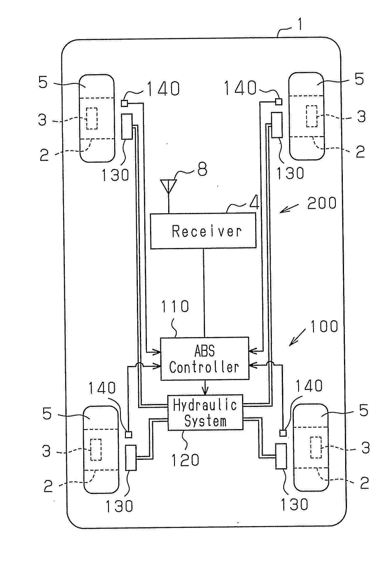
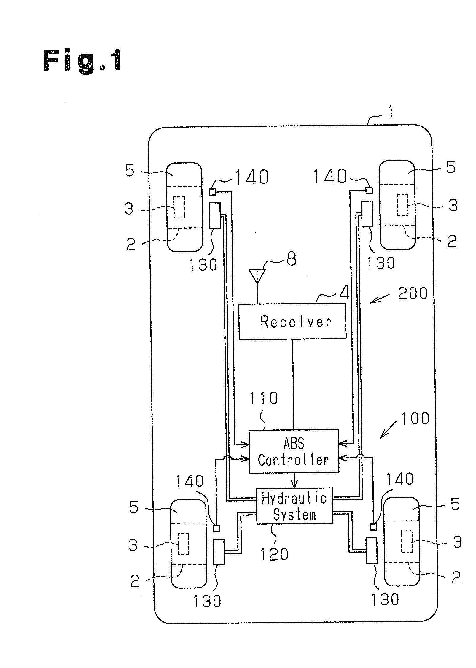
[0022]As shown in FIG. 1, a vehicle 1 is provided with an ABS (anti-lock braking system) 100 and a tire condition monitoring apparatus 200.

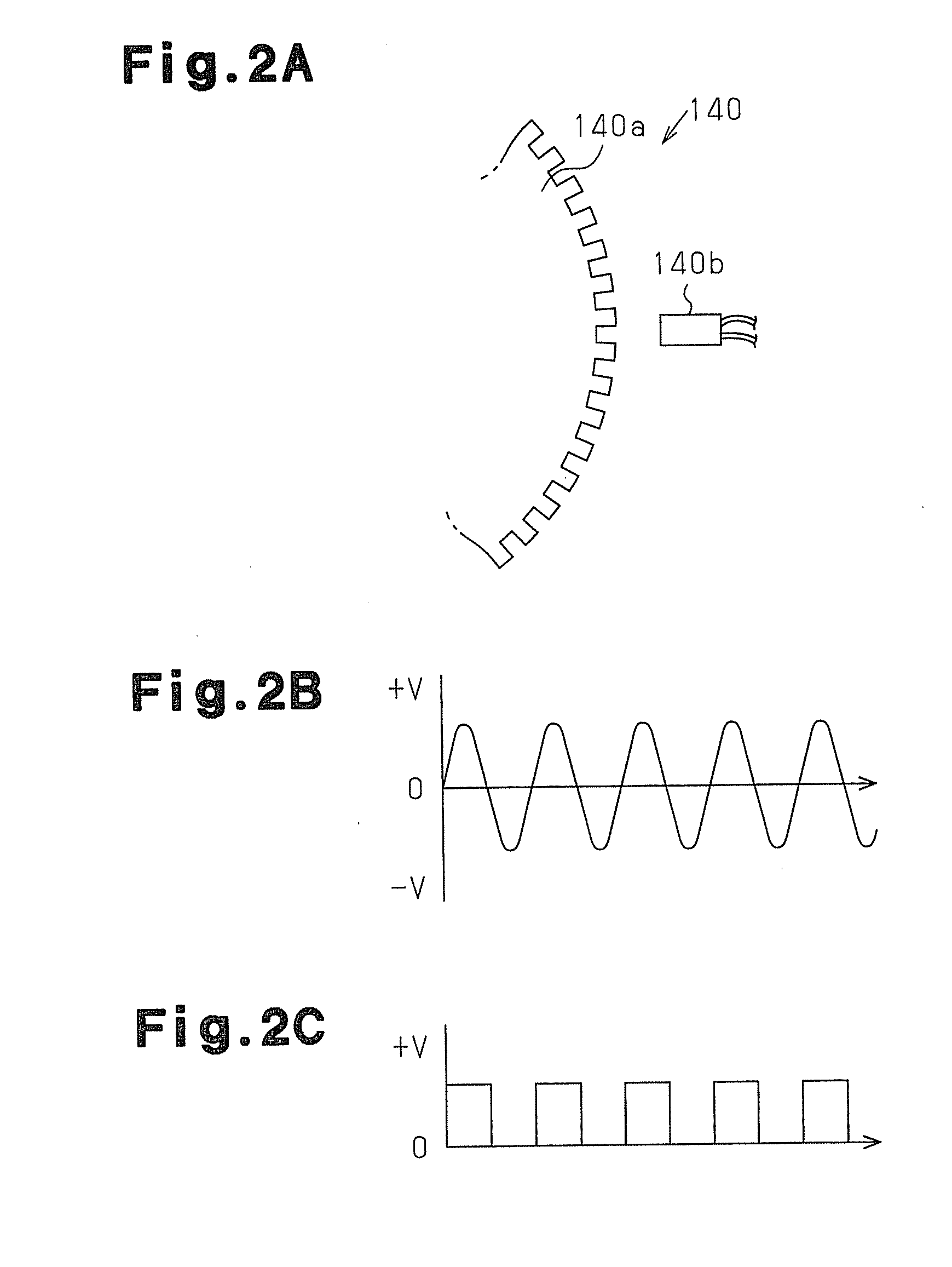
[0023]First, the ABS 100 will be explained. The ABS 100 includes an ABS controller 110, a hydraulic system 120, brake units 130 corresponding to four wheels 2 of the vehicle 1, and rotation sensor units 140 corresponding to the four wheels 2. Each brake unit 130 brakes the corresponding wheel 2 by hydraulic oil supplied from the hydraulic system 120. The ABS controller 110 is configured by a microcomputer including a CPU, a ROM, and a RAM, and computes the rotational speed of each wheel 2 based on signals from the associated rotation sensor unit 140. Based on the rotational speed and the radius of the tire 5 mounted on each wheel 2, the ABS controller 110 computes the moving speed of the wheels 2 with respect to the road surface. The radius of the t...


PUM


Abstract

A vehicle includes an ABS, which controls braking force on wheels, and a tire condition monitoring apparatus, which detects the internal air pressure of tires. The dynamic rolling radius of the tires is computed based on signals from rotation sensor units of the ABS. The weight of a load carried by the vehicle is computed based on the dynamic rolling radius of the tires and the internal air pressure of the tires detected by the tire condition monitoring apparatus. When computing the load weight, a load weight determination map, which previously sets the relationship among the internal air pressure of the tires, the dynamic rolling radius of the tires, and the weight of the load carried by the vehicle, is used.

Description

BACKGROUND OF THE INVENTION[0001]The present invention relates to a vehicle load weight detecting apparatus that detects the weight of a load carried by a vehicle using an ABS and a tire condition monitoring apparatus mounted on the vehicle.[0002]Japanese Patent No. 3578311 and Japanese Laid-Open Patent Publication No. 2005-140503 each disclose a vehicle weight detecting apparatus that detects the total weight of a vehicle or the weight of a load carried by the vehicle.[0003]According to the weight detecting apparatus of Japanese Patent No. 3578311, an air pressure sensor for detecting the internal air pressure of a tire, a temperature sensor for detecting the internal temperature of the tire, and a transmitter, which wirelessly transmits signals representing the detected internal air pressure and internal temperature, are provided on each of vehicle wheels. A receiver, which receives signals from the transmitters, and a measuring apparatus, which computes the weight of the load car...

Claims


Application Information

Patent Timeline
IPC IPC(8): B60C23/04G06F7/00
CPCB60C23/04G01G23/3728G01G19/086
Inventor KATOU, MICHIYA
Owner PACIFIC INDUSTRIAL CO LTD
Learn More