Supercharge Your Innovation With Domain-Expert AI Agents!

Ultrasonic receiver

a receiver and ultrasonic technology, applied in the field of ultrasonic receivers, can solve the problems of reducing efficiency and difficulty in detecting ultrasonic waves with high sensitivity, and achieve the effects of high sensitivity, increased sound pressure of ultrasonic waves received, and high efficiency

Active Publication Date: 2010-07-22
PANASONIC CORP
View PDF9 Cites 5 Cited by
  • Summary
  • Abstract
  • Description
  • Claims
  • Application Information

AI Technical Summary

Benefits of technology

[0031]According to the present invention, by refracting an incoming ultrasonic wave such that the ultrasonic wave goes through an environmental fluid and then is transmitted into a propagation medium portion, the ultrasonic wave can be transmitted through the propagation medium with high efficiency while the reflection of the ultrasonic wave from an interface between two media with mutually different acoustic impedances is minimized. Also, the propagation medium portion is preferably arranged so as to define one surface of the waveguide that is filled with an environmental fluid. And the surface shape of the propagation medium portion in contact with the waveguide is preferably determined such that, as the ultrasonic wave propagates inside the waveguide, each portion of the ultrasonic wave is transmitted into the propagation medium portion one wave after another and then converged toward a predetermined convergence point. Then the ultrasonic wave that has been transmitted one wave after another into the propagation medium portion can be converged toward the convergence point with their phases matched with each other. As a result, the ultrasonic wave can be converged by using the majority of the ultrasonic wave that has come through the opening of the waveguide, and the sound pressure of the ultrasonic wave received can be increased. Consequently, the ultrasonic wave can be detected with high sensitivity.
[0032]Other features, elements, processes, steps, characteristics and advantages of the present invention will become more apparent from the following detailed description of preferred embodiments of the present invention with reference to the attached drawings.

Problems solved by technology

For that reason, it is usually difficult to detect an ultrasonic wave with high sensitivity.
In transmitting an ultrasonic wave from an ultrasonic vibrator into the air, the efficiency will also decrease due to the reflection.
That is why particularly when an ultrasonic wave is used to measure a distance or a flow rate or to sense an object, it is one of the most important problems to detect the ultrasonic wave with high sensitivity.

Method used


Image

  • Ultrasonic receiver
  • Ultrasonic receiver
  • Ultrasonic receiver

Examples


Embodiment Construction

[0069]Hereinafter, preferred embodiments of an ultrasonic receiver according to the present invention will be described with reference to the accompanying drawings.

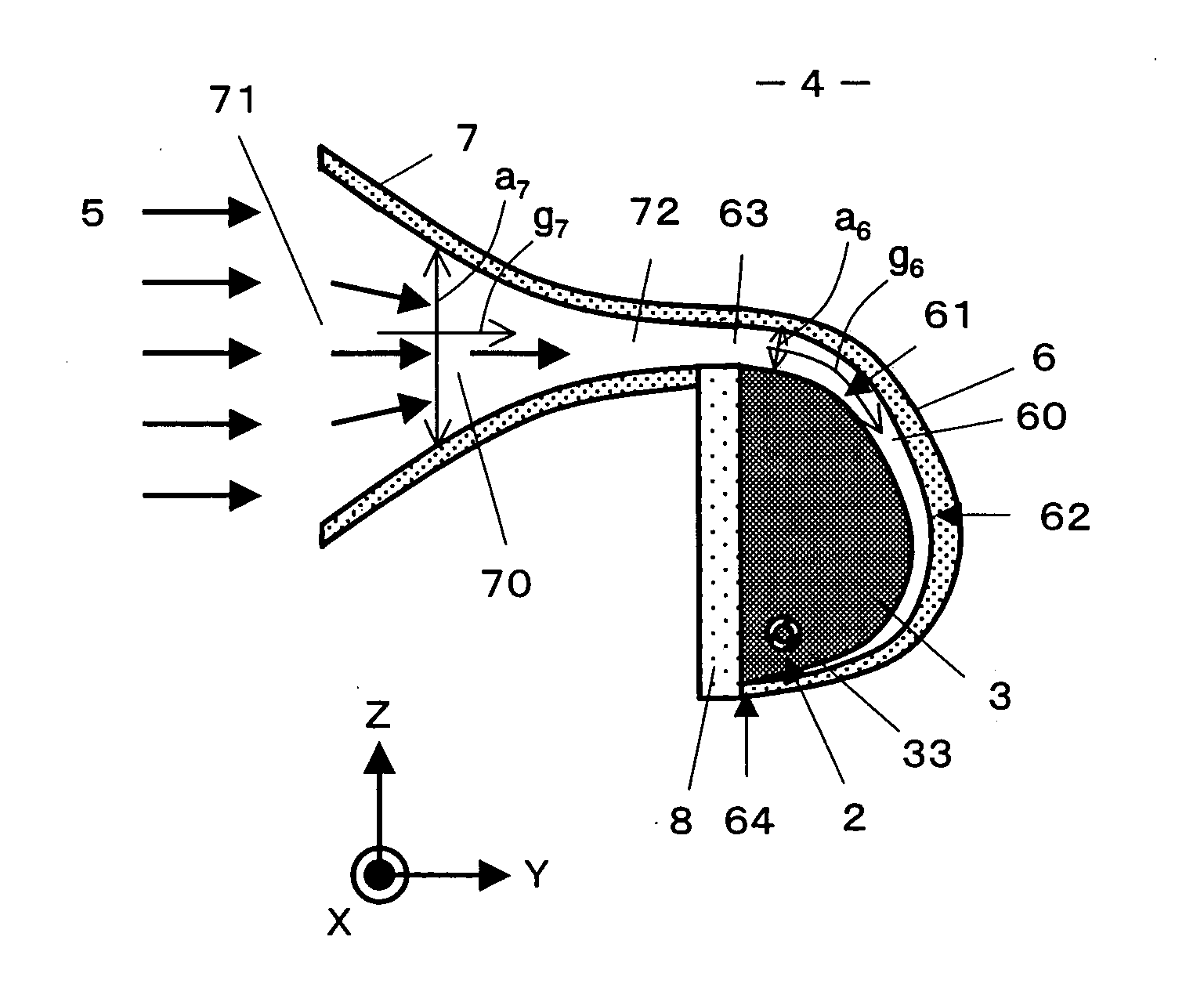
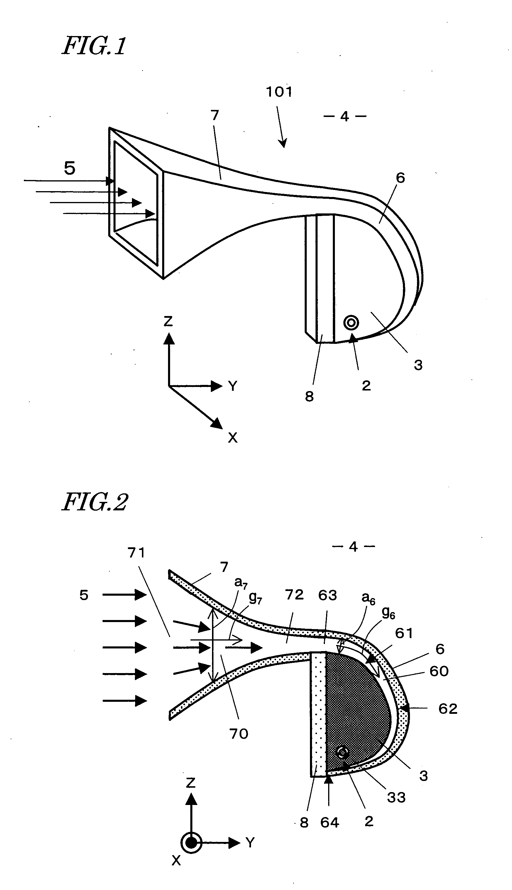
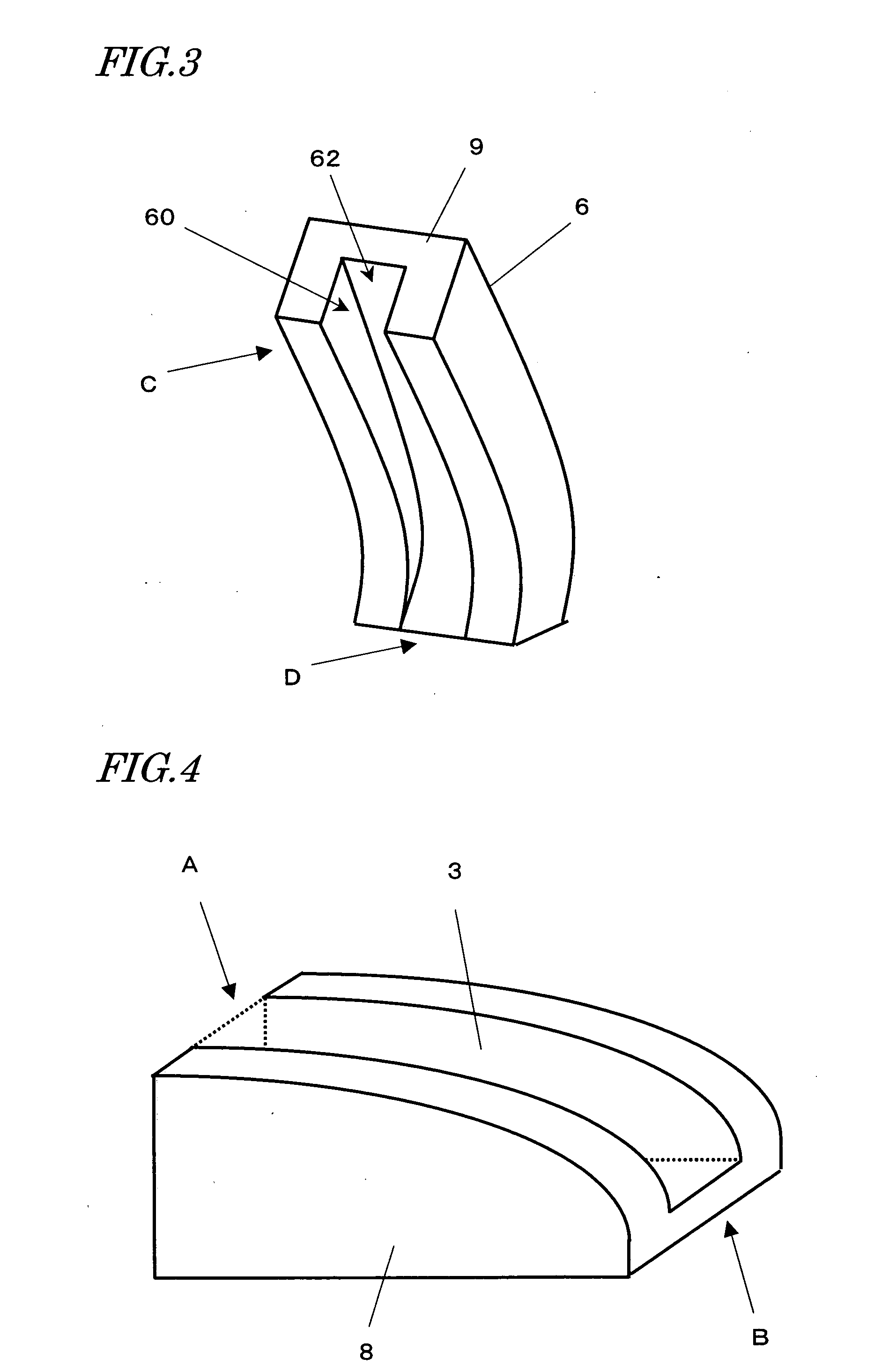
[0070]An ultrasonic receiver according to the present invention makes an incoming ultrasonic wave propagate from an environmental fluid with very small acoustic impedance (such as a gas) into a solid with high efficiency and then gets the ultrasonic wave, transmitted through the solid, converged inside the solid, thereby increasing the energy density of the ultrasonic wave. As a result, the receiver can receive the ultrasonic wave with high sensitivity. The present invention is preferably implemented as an ultrasonic receiver that can be used in various fields of applications. In general, however, an ultrasonic receiver also functions as a transmitter. That is why the present invention is at least applicable to an apparatus that can receive an ultrasonic wave and is preferably applied to an ultrasonic transducer that can ...


PUM


Abstract

An ultrasonic receiver according to the present invention includes: a wave propagating portion 6, which defines a first opening 63 and a waveguide 60 that makes an ultrasonic wave, coming through the first opening 63, propagate in a predetermined direction; and a propagation medium portion 3, which has a transmissive interface 61 and which is arranged with respect to the waveguide 60 such that the transmissive interface 61 defines one surface of the waveguide 60 in the direction in which the ultrasonic wave propagates. The interface 61 is designed and arranged with respect to the waveguide 60 such that as the ultrasonic wave propagates along the waveguide 60, each portion of the ultrasonic wave is transmitted into the propagation medium portion 3 through the interface 61 and then converged toward a predetermined convergence point. The receiver further includes a sensor portion 2, which is arranged at the convergence point 33 to detect the ultrasonic wave converged. The propagation medium portion includes a propagation medium that fills a space between the interface and the convergence point. The waveguide is filled with an environmental fluid and acoustic velocities Cn and Ca of the ultrasonic wave propagating through the propagation medium portion 3 and the environmental fluid 4, respectively, satisfy Cn / Ca<1. If a distance from the first opening of the waveguide to a point P, which is set at an arbitrary location on the transmissive interface, is La as measured in the ultrasonic wave propagating direction and if a distance from the point P to the convergence point is Ln, then La / Ca+Ln / Cn is always constant irrespective of where the point P is located.

Description

TECHNICAL FIELD[0001]The present invention relates to an ultrasonic receiver for receiving or detecting ultrasonic waves.BACKGROUND ART[0002]An ultrasonic wave propagates through a solid and various other media, and therefore, has been used in a wide variety of fields including measurement, evaluation of physical properties, engineering, medicine and biology.[0003]The propagability of an ultrasonic wave through a medium is represented as acoustic impedance. Generally speaking, at an interface between two types of media with significantly different acoustic impedances (such as a gas and a solid), most of the ultrasonic wave that has been propagated through one of those two media will be reflected, and the ultrasonic wave cannot be transmitted to the other medium with high efficiency.[0004]An ultrasonic vibrator is used extensively to detect an ultrasonic wave and is often made of a piezoelectric body such as a ceramic. That is why if an ultrasonic wave that has been propagated throug...

Claims


Application Information

Patent Timeline
IPC IPC(8): G01F1/66
CPCG10K11/30
Inventor NAGAHARA, HIDETOMOSUGINOUCHI, TAKEHIKOHASHIMOTO, MASAHIKO
Owner PANASONIC CORP
Features
  • R&D
  • Intellectual Property
  • Life Sciences
  • Materials
  • Tech Scout
  • Unparalleled Data Quality
  • Higher Quality Content
  • 60% Fewer Hallucinations
Learn More