Ring heat dissipating device formed by punching and riveting through a shaping mold

a heat dissipating device and shaping mold technology, applied in the direction of air heaters, semiconductor devices for light sources, light and heating apparatus, etc., can solve the problems of poor heat dissipation substrate, save production time and procedures, and improve heat dissipation effect.

Inactive Publication Date: 2010-07-22
CHEN SHYH MING
View PDF8 Cites 11 Cited by
  • Summary
  • Abstract
  • Description
  • Claims
  • Application Information

AI Technical Summary

Benefits of technology

[0010]1. Production time and procedures are saved and simplified by combining the bottom plate, ring body, heat dissipating fins together through punching the ring body to fix the heat dissipating fins and punching the bottom plate to fix to the ring body. The material and position of the bottom plate inside the ring body can be adjusted to meet the performance acquired by industrial.
[0011]2. The bottom plate is fixed to the ring body without entire contact, heat dissipating effect is improved by the gaps remained between the assembled bottom plate and the ring body.

Problems solved by technology

Normal LED generates lower heat than a prior light device, but the heat dissipation is still an important issue to take care on a high density area or high power LED on a normal poor heat dissipating substrate.

Method used


Image

  • Ring heat dissipating device formed by punching and riveting through a shaping mold
  • Ring heat dissipating device formed by punching and riveting through a shaping mold
  • Ring heat dissipating device formed by punching and riveting through a shaping mold

Examples


Embodiment Construction

[0027]In order that those skilled in the art can further understand the present invention, a description will be provided in the following in details. However, these descriptions and the appended drawings are only used to cause those skilled in the art to understand the objects, features, and characteristics of the present invention, but not to be used to confine the scope and spirit of the present invention defined in the appended claims.

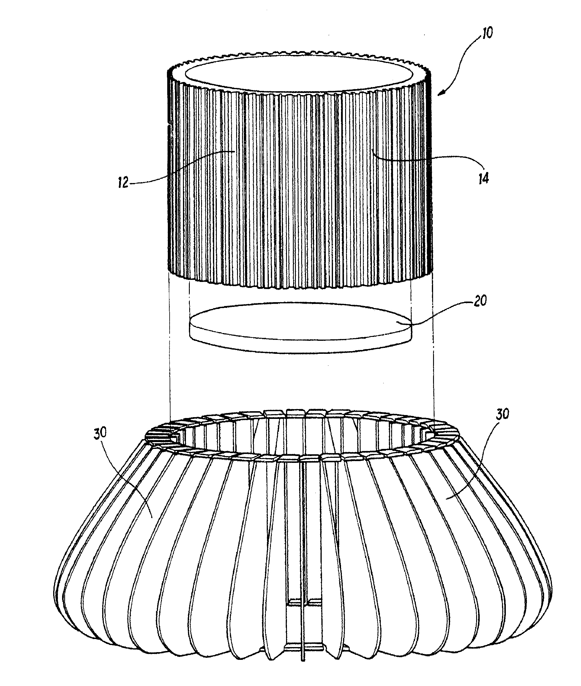
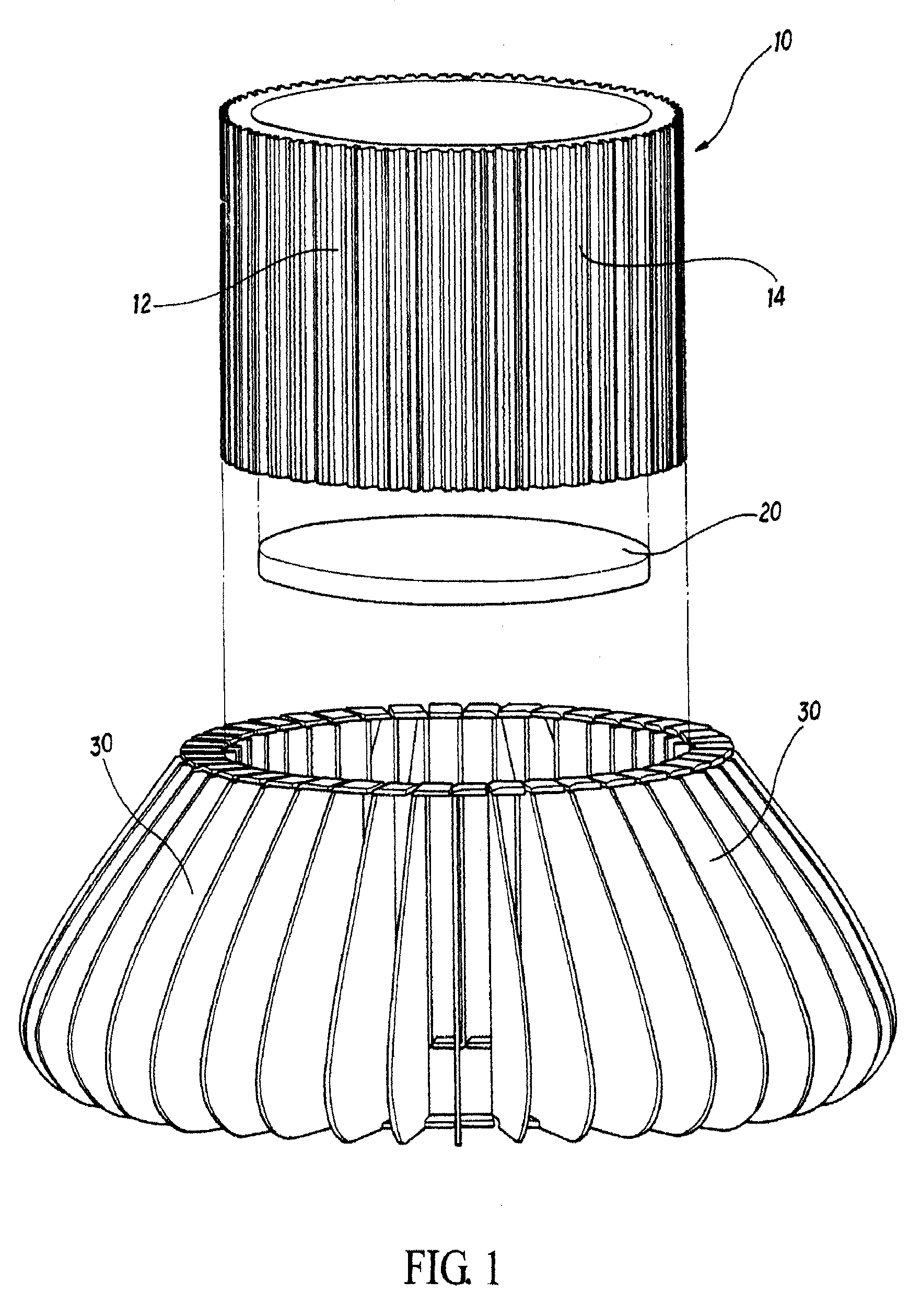
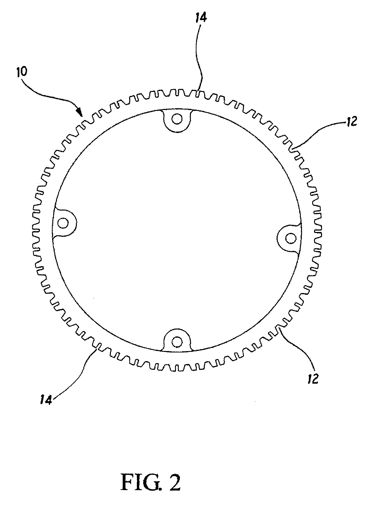
[0028]Referring to FIG. 1, the present invention is mainly assembled by a ring body 10, a bottom plate 20 arranged inside the ring body 10, and a plurality of heat dissipating fins 30 arranged outside the ring body 10. As shown in FIG. 2, the ring body 10 is a hollow cylinder body with a plurality of trenches 12 and slots 14 formed one next to one on an outer surface thereof. The shape of the ring body 10 is not confined in practice. The material of the bottom plate 20 can be chosen by a metal of well thermal conductivity such as cooper, aluminum, ...


PUM


Abstract

A ring heat dissipating device is mainly assembled by a ring body, a bottom plate arranged inside the ring body, and a plurality of heat dissipating fins arranged outside the ring body. The bottom plate is punched by a mold so that the bottom plate is fixed to a predetermined position inside the ring body. The heat dissipating fins are inserted into slots on an outer surface of the ring body. After trenches between the slots are punched and deformed, the heat dissipating fins are tightly riveted by the deformed trenches.

Description

FIELD OF THE PRESENT INVENTION[0001]The present invention relates to heat dissipating devices, and particular to an improved structure of combining a ring body, heat dissipating fins, and a bottom plate together by punching and riveting.DESCRIPTION OF THE PRIOR ART[0002]By the higher and higher performance of the electronics and electrical products, the consumed power is higher as well as heat being generated. To dissipate the heat to stabilize the performance of the electronics becomes an important subject of product design.[0003]Heat dissipation is a very important part in manufacturing of electronic products and electronics. Higher requirements in heat dissipating come with the changing market of advance consuming products. For example, familiar lamps like tungsten lamsp and electric bulbs are replaced by light emitting diodes (LEDs) which has advantage of low power consumption, long life time, and high power and others. LEDs are widely used as a lighting device in panels of elec...

Claims


Application Information

Patent Timeline
Patent Type & Authority Applications(United States)
IPC IPC(8): H05K7/20F28F7/00
CPCF21K9/00F28F1/20H01L21/4878H01L21/4882H01L23/3672F21V29/77H01L2924/0002F21V29/773F21V29/89H01L2924/00F21V29/70
Inventor CHEN, SHYH MING
Owner CHEN SHYH MING
Why Eureka
Try Eureka