Monitoring and control device

Active Publication Date: 2010-07-22
PANASONIC CORP
View PDF12 Cites 26 Cited by
  • Summary
  • Abstract
  • Description
  • Claims
  • Application Information

AI Technical Summary

Benefits of technology

[0035]With such configuration, even if when the locking claws are removed from the locking holes, the drop-preventing lugs 1025 is brought contact with the front wall portion of the plate cover, thereby preventing the panel unit from being dropped. Further, the panel unit is detachably attached to the front surface of the body unit from the f

Problems solved by technology

This makes it impossible to specify one of the switches to be actually operated.
This poses a problem of increasing the space occupied by an operation terminal.
This necessitates use of an operation unit for performing the setting noted above, consequently increasing the number of switches required and increasing the space occupied by the operation terminal.
This reduces the efficiency of the setting task.
Thus, an abnormal current may flow through the connectors of the body unit and the panel unit.
As a result, there is a possibility that failure or other trouble may occur in the body unit or the panel unit.
However, such a movable part as the operating member of the mechanical switch makes the structure of the body unit complicated.
However, if the operating member of the me

Method used


Image

  • Monitoring and control device
  • Monitoring and control device
  • Monitoring and control device

Examples


first embodiment

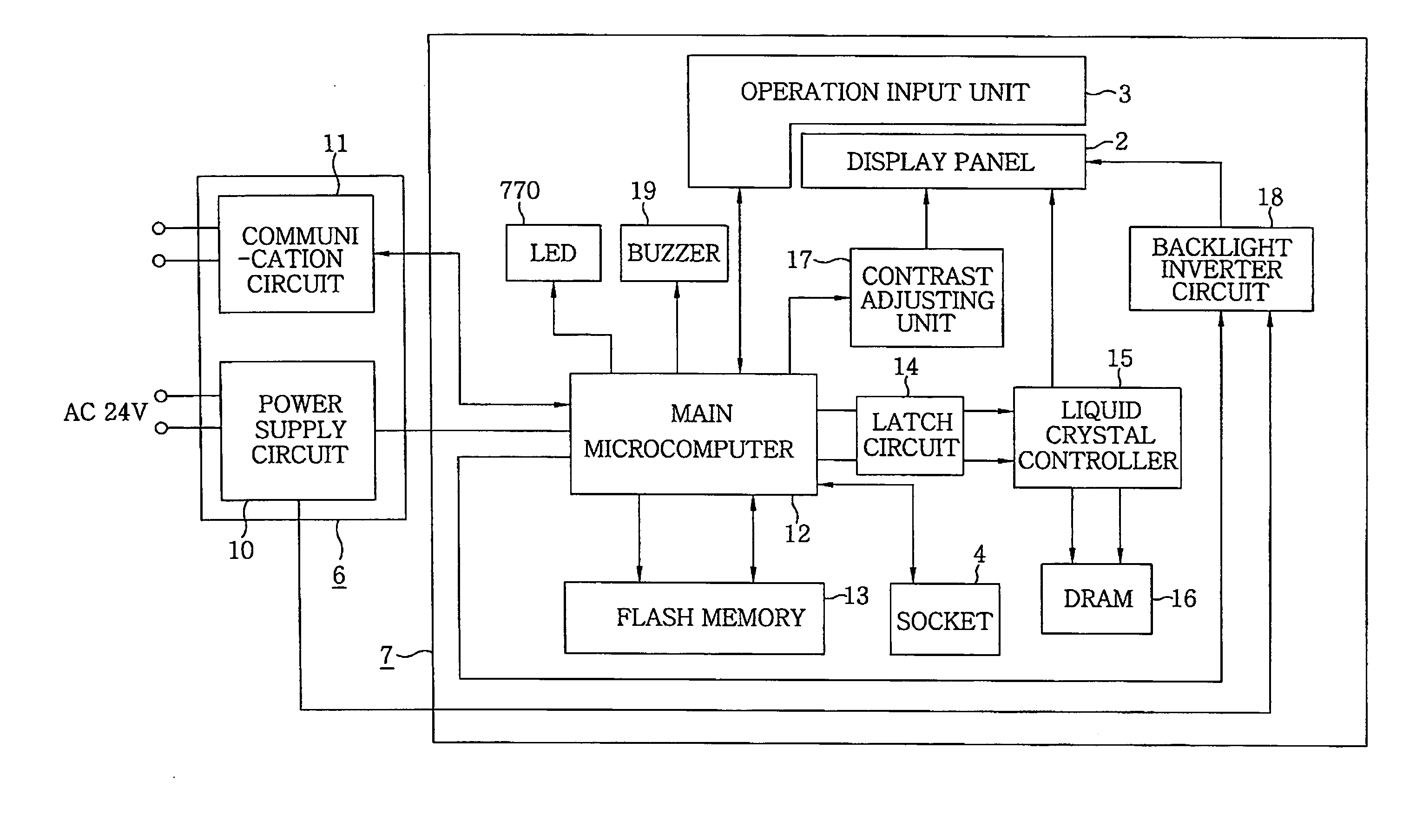
[0073]Referring to FIG. 3, the monitoring and control device of the present embodiment includes a display panel 2 formed by combining a backlight with a liquid crystal display, and an operation input unit 3 formed of a transparent flat touch switch superimposed on the screen (or the front surface) of the display panel 2. The display panel 2 is of a matrix display type in which a multiplicity of pixels is arranged in a matrix pattern. A pictorial figure is represented by the combination of pixels. The operation input unit 3 includes a transparent sheet member and a plurality of transparent electrode contact points arranged on the sheet member. The operation input unit 3 is a resistance-pressure-sensitive touch switch that outputs a signal indicating the point on the sheet member touched by a finger or the like. The display panel 2 and the operation input unit 3 cooperate to form a touch panel display.

[0074]The monitoring and control device 1 further includes a communication circuit 1...

second embodiment

[0107]A monitoring and control device in accordance with a second embodiment of the present invention will now be described with reference to FIG. 11. The same component parts as those of the first embodiment will be designated by like reference characters and will be omitted from description.

[0108]As shown in FIG. 11, the body unit 6 includes a power supply terminal portion T1 to which the power supply line is connected and a signal terminal portion T2 to which the signal line Ls is connected. The power supply terminal portion T1 and the signal terminal portion T2 are arranged on the rear surface of the body unit 6.

[0109]In the monitoring and control device 1 of the present embodiment, as shown in FIG. 11, the body unit 6 includes a detection unit 21 for detecting the connection between the body-side connector 68 and the panel-side connector 80 and a power supply control unit 22 for on-off controlling the power supply from the power supply circuit 10 to the body-side connector 68. ...

third embodiment

[0125]The monitoring and control device 1 of the present embodiment differs from that of the second embodiment in that detection pins are provided at a plurality of points of the body-side connector 68 and the panel-side connector 80.

[0126]In the present embodiment, as shown in FIG. 12, a detection pin P1a is provided in the left end portion (i.e., the lower end portion in FIG. 12) of the body-side connector 68, a detection pin P2a being provided in the medial portion, a detection pin P3a being provided in the right end portion. Detection pins P1b, P2b and P3b are provided in the portions of the panel-side connector 80 corresponding to the detection pins P1a, P2a and P3a. The detection pins P1b, P2b and P3b of the panel-side connector 80 are connected to the corresponding detection current lines Le1, Le2 and Le3. Detection power sources 23 are provided in a corresponding relationship with the respective detection current lines Le1, Le2 and Le3 (namely, the detection pins P1a, P2a an...


PUM


Abstract

In a monitoring and control device for use in a remote monitoring and control system, a device housing has a socket located behind a display panel and an external storage medium including a rewritable memory is removably mounted in the socket. The device housing is attached in an attachment hole formed in a wall in a state that the external storage medium is mounted in the socket. A control unit performs a setting operation for a graphic image displayed on the display panel and for the load control in accordance with setting information stored in the external storage medium. The external storage medium is inserted in the socket through an insertion slot formed in a side portion of the device housing, at least a portion of the insertion slot being received in the attachment hole in a state that the device housing is attached to the wall.

Description

FIELD OF THE INVENTION[0001]The present invention relates to a monitoring and control device for use in a remote monitoring and control system that performs monitoring and control of a load through communication.BACKGROUND OF THE INVENTION[0002]Conventionally, there are known remote monitoring and control systems for performing remote monitoring and control of a load, in which a transmission signal containing switch on-off information is transmitted through a signal line and in which a relay for turning on or off the electric power supplied to the load is opened and closed by the transmission signal.[0003]One example of these remote monitoring and control systems is a centralized control system that includes a terminal device formed of an operation terminal having a switch and a control terminal having a relay for turning on or off the electric power supplied to a load and a central device formed of a transmission unit. Each of the operation terminal and the control terminal may be ...

Claims


Application Information

Patent Timeline
IPC IPC(8): G06F3/041G09G5/00
CPCG06F1/1601G09G3/2096G09G3/3406G09G2330/028H05K5/0017H05K5/0018
Inventor YOSHIKAWA, KEISUKESASAKI, TOMOAKIKIMURA, KATSUHIKOMIURA, KEIHIROISHI, AKIHIROKITAMURA, SATOSHINAOI, YULCHIROKAWAMATA, MOTOTSUGUYOSHIMURA, YUICHI
Owner PANASONIC CORP
Why Eureka
Try Eureka