Phase locked loop capable of fast locking

a phase lock and loop technology, applied in the direction of phase difference detection, pulse automatic control, angle demodulation, etc., can solve the problem that the conventional phase lock loop using frequency switching cannot achieve fast locking

a phase lock and loop technology, applied in the direction of phase difference detection, pulse automatic control, angle demodulation, etc., can solve the problem that the conventional phase lock loop using frequency switching cannot achieve fast locking

US20100183109A1Active Publication Date: 2010-07-22NAT TAIWAN UNIV

Image

  • Phase locked loop capable of fast locking
  • Phase locked loop capable of fast locking
  • Phase locked loop capable of fast locking

Examples


Embodiment Construction

[0035]Before the present invention is described in greater detail, it should be noted that like elements are denoted by the same reference numerals throughout the disclosure.

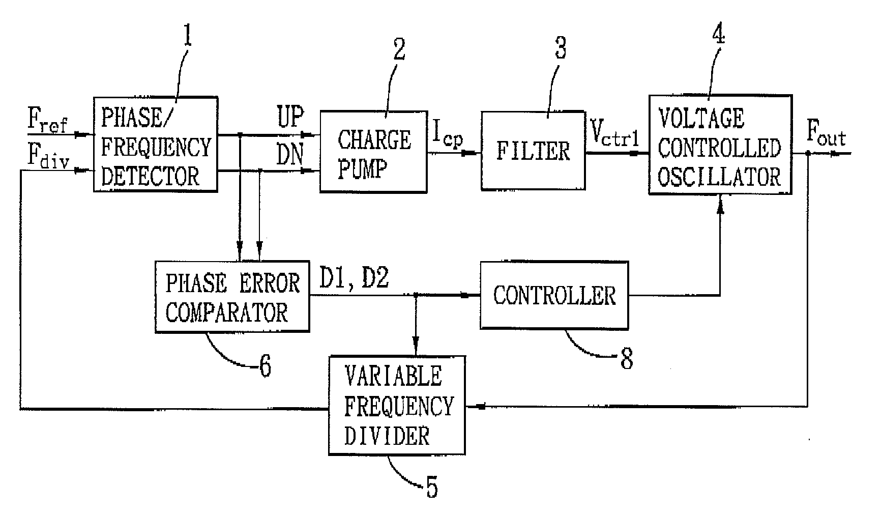
[0036]Referring to FIG. 4, the first preferred embodiment of a phase locked loop according to the present invention is shown to include a phase / frequency detector 1, a charge pump 2, a filter 3, a voltage controlled oscillator 4, a variable frequency divider 5, and a phase error comparator 6.

[0037]The voltage controller oscillator 4 is operable so as to generate an output signal (Fout) corresponding to a reference signal (Fref) in response to at least a control voltage signal (Vctrl) received thereby.

[0038]The variable frequency divider 5 is coupled to the voltage controlled oscillator 4 for receiving the output signal (Fout) therefrom, and is operable to perform frequency division on the output signal (Fout) using a variable divisor so as to generate a divided feedback signal (Fdiv).

[0039]The phase / frequency de...


PUM


Abstract

A phase locked loop includes a voltage controlled oscillator operable to generate an output signal corresponding to a reference signal in response to a control voltage signal outputted by a filter in response to a current signal, and a variable frequency divider operable to perform frequency division on the output signal using a variable divisor so as to generate a divided feedback signal. A charge pump outputs the current signal in response to a phase detecting output from a phase / frequency detector indicating phases of the divided feedback signal and the reference signal. A phase error comparator outputs, in accordance with the phase detecting output, a digital output indicating whether the divided feedback signal lags or leads the reference signal and further indicating a phase difference between the divided feedback signal and the reference signal. The variable frequency divider determines a value of the variable divisor in accordance with the digital output to reduce the phase difference between the divided feedback signal and the reference signal .

Description

CROSS-REFERENCE TO RELATED APPLICATION[0001]This application claims priority of Taiwanese Application No. 098102236, filed on Jan. 21, 2009.BACKGROUND OF THE INVENTION[0002]1. Field of the Invention[0003]The invention relates to a phase locked loop, more particularly to a phase locked loop capable of dynamic phase compensation during frequency locking.[0004]2. Description of the Related Art[0005]Phase locked loops are commonly used in a wireless communication system requiring frequencies with high accuracy FIG. 1 illustrates a conventional phase locked loop 1 that includes a phase / frequency detector 11, a charge pump 12, a filter 13, a voltage controlled oscillator 15, and a frequency divider 15 connected in a feedback loop.[0006]The phase / frequency detector 11 detects a reference signal (Fref), and a divided feedback signal (Fdiv) generated by the frequency divider 15 through frequency division on an output signal (Fout) from the voltage controlled oscillator 14, and outputs a phas...

Claims


Application Information

Patent Timeline
22 Jul 2010
Publication
US20100183109A1
IPC
H03D3/24
CPC
H03L7/081; H03L7/085; H03L7/0893; H03L7/1075; H03L2207/06
Inventors
LIN, TSUNG-HSIEN; CHIU, WEI-HAO