Mobile communication system for low power consumption, call control server and access gateway

a mobile communication system and power consumption technology, applied in the field of mobile communication systems, can solve the problems of increasing the power consumption of the processor and increasing the ict equipment, and achieve the effect of reducing the power consumption of the system

Inactive Publication Date: 2010-07-22
HITACHI LTD
View PDF11 Cites 77 Cited by
  • Summary
  • Abstract
  • Description
  • Claims
  • Application Information

AI Technical Summary

Benefits of technology

[0013]According to a representative embodiment of this invention, it is possible to reduce the power consumption of t

Problems solved by technology

Therefore, power consumption of the processor tends to increase due to the increased number of processors or increased clock.
Further, as in the background of the proposed green ICT, an incr

Method used


Image

  • Mobile communication system for low power consumption, call control server and access gateway
  • Mobile communication system for low power consumption, call control server and access gateway
  • Mobile communication system for low power consumption, call control server and access gateway

Examples


first embodiment

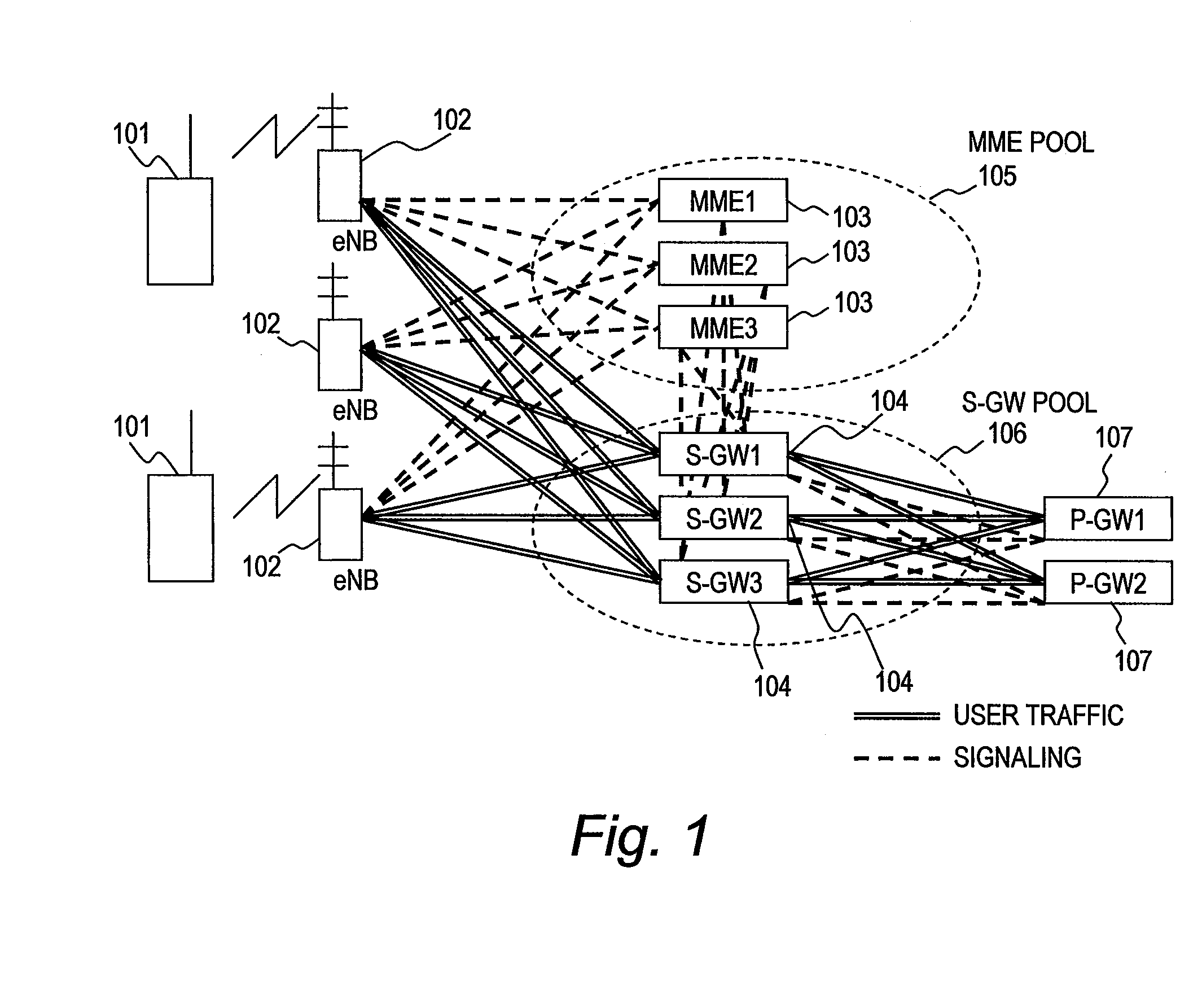
[0034]FIG. 1 is an explanatory diagram illustrating an example of a configuration of a mobile communication system according to a first embodiment of this invention.

[0035]FIG. 1 illustrates an example of a configuration of a long term evolution (LTE) system being a 3.9-generation mobile communication system.

[0036]The mobile communication system according to the first embodiment includes a plurality of base stations (eNBs: eNodeBs) 102, a plurality of mobility management entities (MME, mobility management call control servers) 103, a plurality of service gateways (S-GWs) 104, and a plurality of packet data network gateways (P-GWs) 107. The base station 102 connects a line to a user entity 101 located in a tracking area (a location area) of its own station.

[0037]The MME 103 receives a tracking area update request (a location registration request) transmitted from the user entity (mobile terminal) 101. Further, the MME 103 executes location management of the user entity 101, an authent...

second embodiment

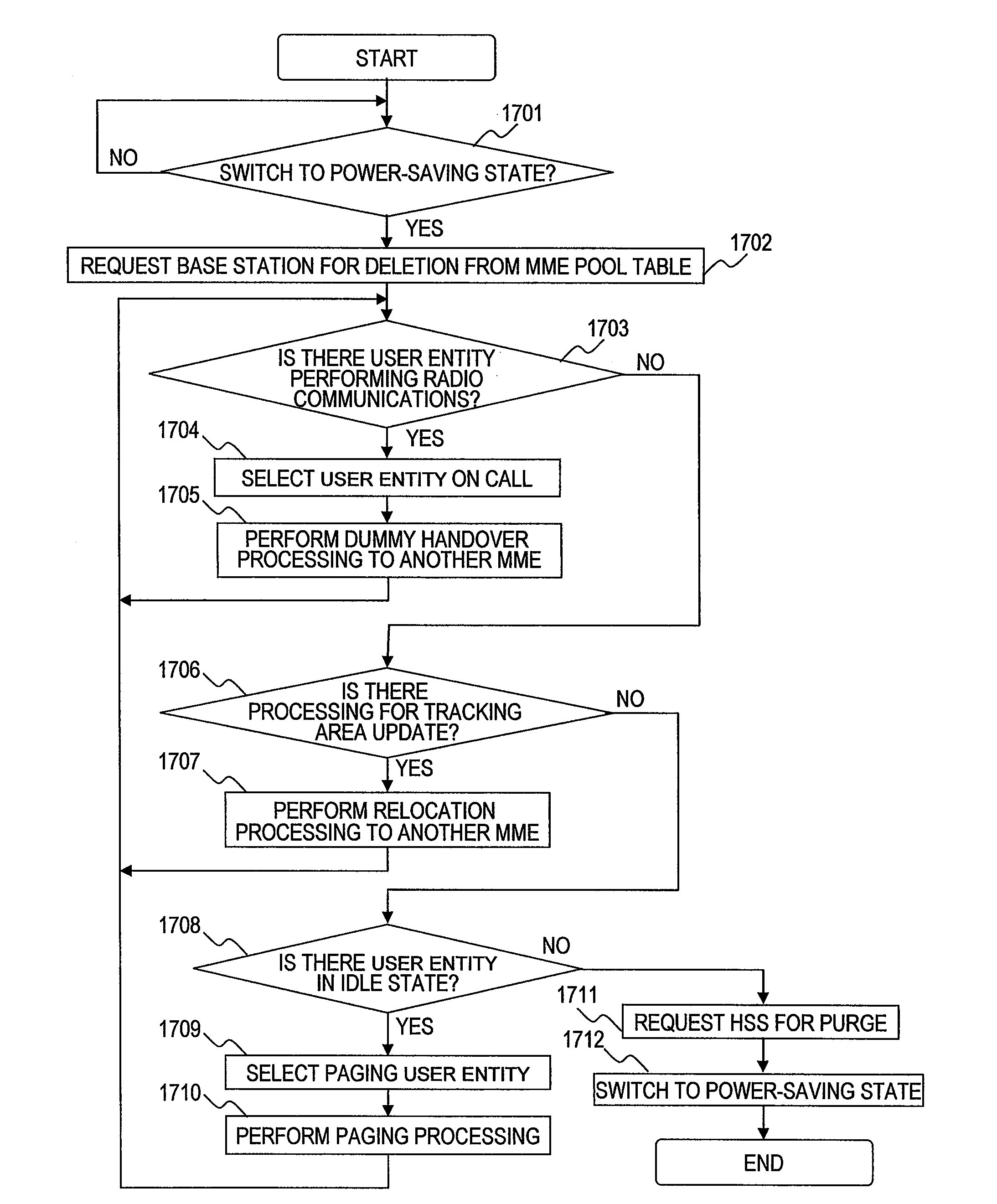
[0127]Hereinafter, description is made of a processing of reaccommodating the user entity 101 in the idle state accommodated in the CPU blade 201 that operates as the MME 103 (and the S-GW 104) into another CPU blade 201.

[0128]FIG. 12 is a sequential diagram illustrating a processing for relocation of the user entity in the idle state according to a second embodiment of this invention.

[0129]A user entity (UE) 1201 is the user entity 101 in the idle state. A base station (eNodeB) 1202 is the base station 102 that communicates with the user entity 1201. A source MME 1203 is the MME 103 at the relocation source. A target MME 1204 is the MME 103 at the relocation target. A source S-GW 1205 is the S-GW 104 at the relocation source. A target S-GW 1206 is the S-GW 104 at the relocation target. A P-GW 1207 is the P-GW 107 that provides the user entity 1201 with a service. A home subscriber server (HSS) 1208 is a server for managing the location of the user entity 1201.

[0130]First, the user ...

third embodiment

[0155]Hereinafter, description is made of a processing of relocating the user entity 101 in the idle state which is accommodated in each of the CPU blades 201 operating as the MMEs 103 (and S-GWs 104) to another CPU blade 201 by changing a tracking area ID (TAI) included in the broadcasting control channel (BCCH) transmitted from the base station 102.

[0156]FIG. 15 is a sequential diagram illustrating a processing for relocation of the user entity in the idle state according to a third embodiment of this invention.

[0157]A user entity (UE) 1501 is the user entity 101 that executes the tracking area update based on a change of the tracking area ID (TAI) included in the received broadcasting control channel. A base station (eNodeB) 1502 is the base station 102 that changes the TAI of the broadcasting control channel. A source MME 1503 is the MME 103 at the relocation source. A target MME 1504 is the MME 103 at the relocation target. A source S-GW 1505 is the S-GW 104 at the relocation s...


PUM


Abstract

It is provided a mobile communication system comprising base stations, call control servers and access gateways. The call control servers cause a mobile terminal accommodated in one of the control server to transmit the location registration request so that the mobile terminal accommodates in another control server according to a processing amount of control signals. The base station selects a second call control server into which the one of the mobile terminals is to be newly accommodated. The one of the call control server switches to a power-saving state after the mobile terminal is accommodated into the another call control server.

Description

CLAIM OF PRIORITY[0001]The present application claims priority from Japanese patent application JP 2009-012156 filed on Jan. 22, 2009, the content of which is hereby incorporated by reference into this application.BACKGROUND OF THE INVENTION[0002]This invention relates to a mobile communication system that provides an IP access service, and more particularly, to a system that reduces power consumption of nodes.[0003]At present, there is provided a 3.5-generation mobile communication service. This service has been allowing an upgraded environment in which a mobile terminal uses connection to the Internet for electronic mail, access to the WEB, and the like.[0004]Further, as a 3.9-generation mobile communication system, worldwide interoperability for microwave access (WiMAX) and long term evolution (LTE) are being developed, and standardization thereof is underway. WiMAX and LTE are next-generation mobile communication systems for realizing high speed that exceeds 10 Mbps at a wider b...

Claims


Application Information

Patent Timeline
IPC IPC(8): H04W4/00H04W36/00G08C17/00
CPCH04W28/08H04W36/12Y02D70/146Y02D70/1262Y02D70/1224H04W60/02Y02D30/70H04W52/0203H04W28/0917H04W28/0831
Inventor YANO, MASASHINAKAMURA, HITOMITAKATORI, MASAHIROMORISHIGE, TAKEHIROSHIMIZU, YOSHIHIRO
Owner HITACHI LTD
Why Eureka
Try Eureka