Speed Change Transmission System

a transmission system and transmission shaft technology, applied in fluid gearings, transmission casings, transportation and packaging, etc., can solve the problems of small size in the fore and aft direction of the transmission case, compact size, etc., to achieve effective absorption of torque variations in the double transmission state, high transmission efficiency of the clutches, and effective absorption of torque variations

Active Publication Date: 2010-07-22
KUBOTA LTD
View PDF8 Cites 24 Cited by
  • Summary
  • Abstract
  • Description
  • Claims
  • Application Information

AI Technical Summary

Benefits of technology

[0061]As in the embodiment of this invention, claws clutches engageable by hydraulic pressurization are used as the speed range setting clutches when a double transmission state is produced, or friction clutches are used on the first transmission shaft and second transmission shaft when claws clutches are used as the speed range setting clutches, to absorb torque variations in the double transmission state by slipping of the clutches. Besides absorbing torque variations in the double transmission state by the clutches, the hydrostatic stepless transmission absorbs the torque variations effectively by slipping of pressure oil. Absorption of the torque variations in the double trans...

Problems solved by technology

Yet, the size in the fore and aft direction ...

Method used


Image

  • Speed Change Transmission System
  • Speed Change Transmission System
  • Speed Change Transmission System

Examples


first embodiment

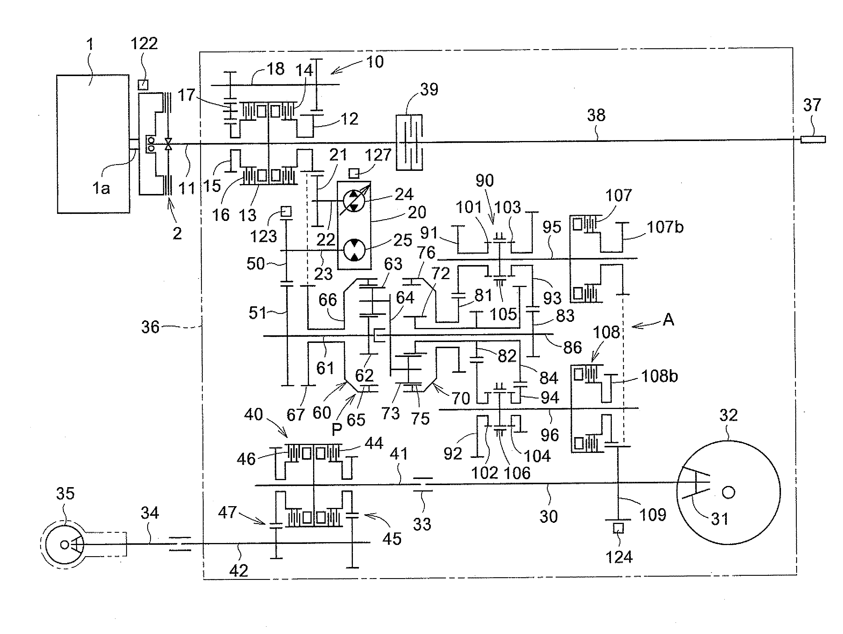
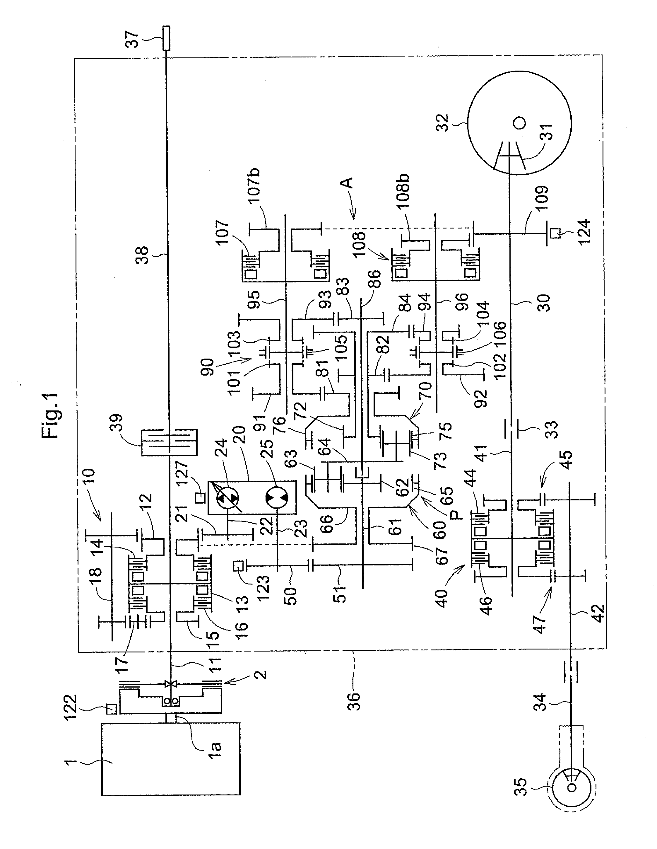
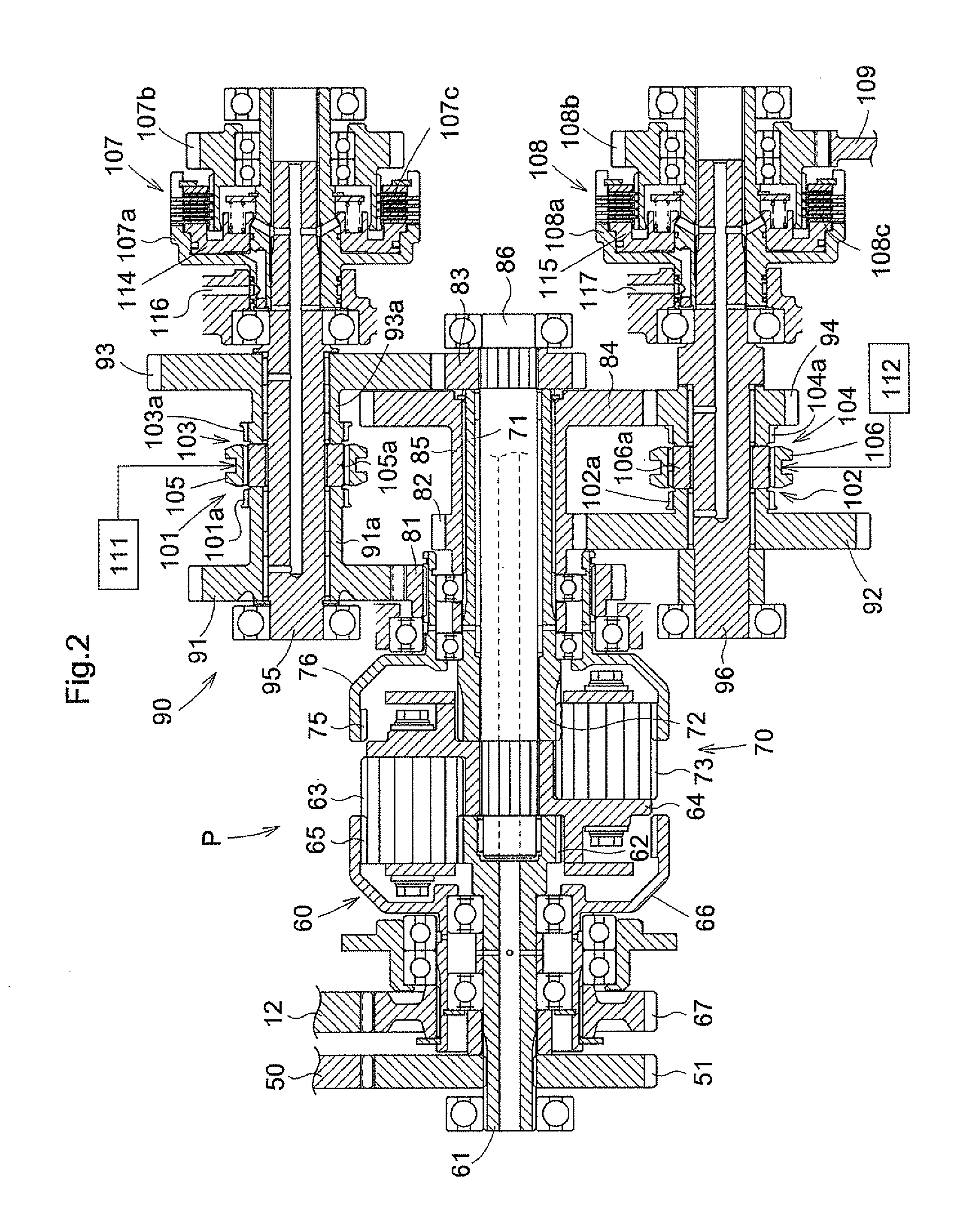
[0085]As shown in FIG. 1, the speed change transmission system A in this invention includes, besides the input shaft 22 and output shaft 30, the stepless transmission 20, the planetary transmission device P having a sun gear shaft 61 interlocked to a motor shaft 23 of the stepless transmission 20 through a gear 50 and a gear 51, and a speed range setter 90 having a first input gear 91 meshed with a first output gear 81 of the planetary transmission device P.

[0086]As shown in FIG. 1, the stepless transmission 20 includes a hydraulic pump 24 of the axial plunger type and variable displacement type having the input shaft 22 as a pump shaft (the input shaft being hereinafter called the pump shaft 22), and a hydraulic motor 25 of the axial plunger type driven by pressure oil from the hydraulic pump 24. The hydraulic motor 25 has the motor shaft 23.

[0087]That is, the stepless transmission 20 is a hydrostatic stepless transmission switchable to a forward rotational transmission state, a ne...

second embodiment

[0145]FIG. 9 is a line map of a traveling transmission system of a tractor equipped with a speed change transmission system A in this invention.

[0146]In the traveling transmission system of the tractor equipped with the speed change transmission system A in the second embodiment of this invention, output from output shaft 30 acting as output rotary member of the speed change transmission system A to a rear wheel differential mechanism 32 and a front wheel change speed device 40 through a forward and backward changeover device 10.

[0147]As shown in FIGS. 9, 10 and 11, the forward and backward changeover device 10 includes an input side rotary member 13 mounted on the output shaft 30 to be rotatable together, output gears 19a and 19b located at the front and rear of this input side rotary member 13, a forward drive friction clutch 14 mounted between one end of the input side rotary member 13 and the front output gear 19a, a backward drive friction clutch 16 mounted between the other en...

third embodiment

[0157]FIG. 12 is a line map of a traveling transmission system of a tractor equipped with a speed change transmission system A in this invention.

[0158]In the traveling transmission system of the tractor equipped with the speed change transmission system A in the third embodiment of this invention, output from output shaft 30 acting as output rotary member of the speed change transmission system A to a rear wheel differential mechanism 32 and a front wheel change speed device 40 through a forward and backward changeover device 10.

[0159]As shown in FIGS. 12, 13 and 14, the forward and backward changeover device 10 in the traveling transmission system equipped with the speed change transmission system A in the third embodiment has the same construction as the forward and backward changeover device 10 in the traveling transmission system equipped with the speed change transmission system A in the second embodiment.

[0160]When the speed change transmission system A in the third embodiment...


PUM


Abstract

In order to provide a speed change transmission system which can be obtained compactly, while obtaining output at steplessly varied speeds over a large speed change range only by carrying out a simple shifting operation, the speed change transmission system has a hydrostatic stepless transmission to which engine drive is inputted. A planetary transmission device (P) has a plurality of planetary transmission mechanisms, for combining output of the stepless transmission and engine drive not undergoing speed change action by the hydrostatic stepless transmission. A plurality of transmission shafts are provided with a plurality of speed range setting clutches, switchable for converting the combined driving force from the planetary transmission device (P) to a driving force in a plurality speed ranges, and transmitting it to an output rotary member. The plurality of transmission shafts are juxtaposed and arranged in parallel.

Description

TECHNICAL FIELD[0001]The present invention relates to a speed change transmission system, and more particularly to a speed change transmission system having a hydrostatic stepless transmission to which engine drive is inputted, and a planetary transmission device having a plurality of planetary transmission mechanisms for combining output of the hydrostatic stepless transmission and the engine drive not undergoing change speed action by the hydrostatic stepless transmission, wherein a combined driving force from the planetary transmission device is stage-divided into a plurality of speed ranges, and each stage of speed range is put to stepless speed changing to be outputted from an output rotary member.BACKGROUND ART[0002]In the above change speed transmission system, the stepless transmission is shiftable to stage-divide a combined driving force of engine output and the output of the stepless transmission or a combined driving force of engine output and the output of an electric mo...

Claims


Application Information

Patent Timeline
IPC IPC(8): F16H47/04
CPCF16H3/18F16H47/04F16H2037/0886F16H2200/2007F16H2200/201F16H2200/2041F16H3/091F16H3/44F16H47/06
Inventor HIRAOKA, MINORUMACHIDA, SATOSHIKATAYAMA, YOSHIYUKI
Owner KUBOTA LTD
Why Eureka
Try Eureka