Methods and systems for material fixation
a technology of material fixation and methods, applied in the field of devices, systems and methods for material fixation, can solve the problems of difficulty in achieving the effect of achieving the effect of reducing the difficulty of traditional techniques used to fix tendon to bone, reducing the difficulty of traditional techniques, and improving the quality of traditional methods
- Summary
- Abstract
- Description
- Claims
- Application Information
AI Technical Summary
Benefits of technology
Problems solved by technology
Method used
Image
Examples
embodiment 110
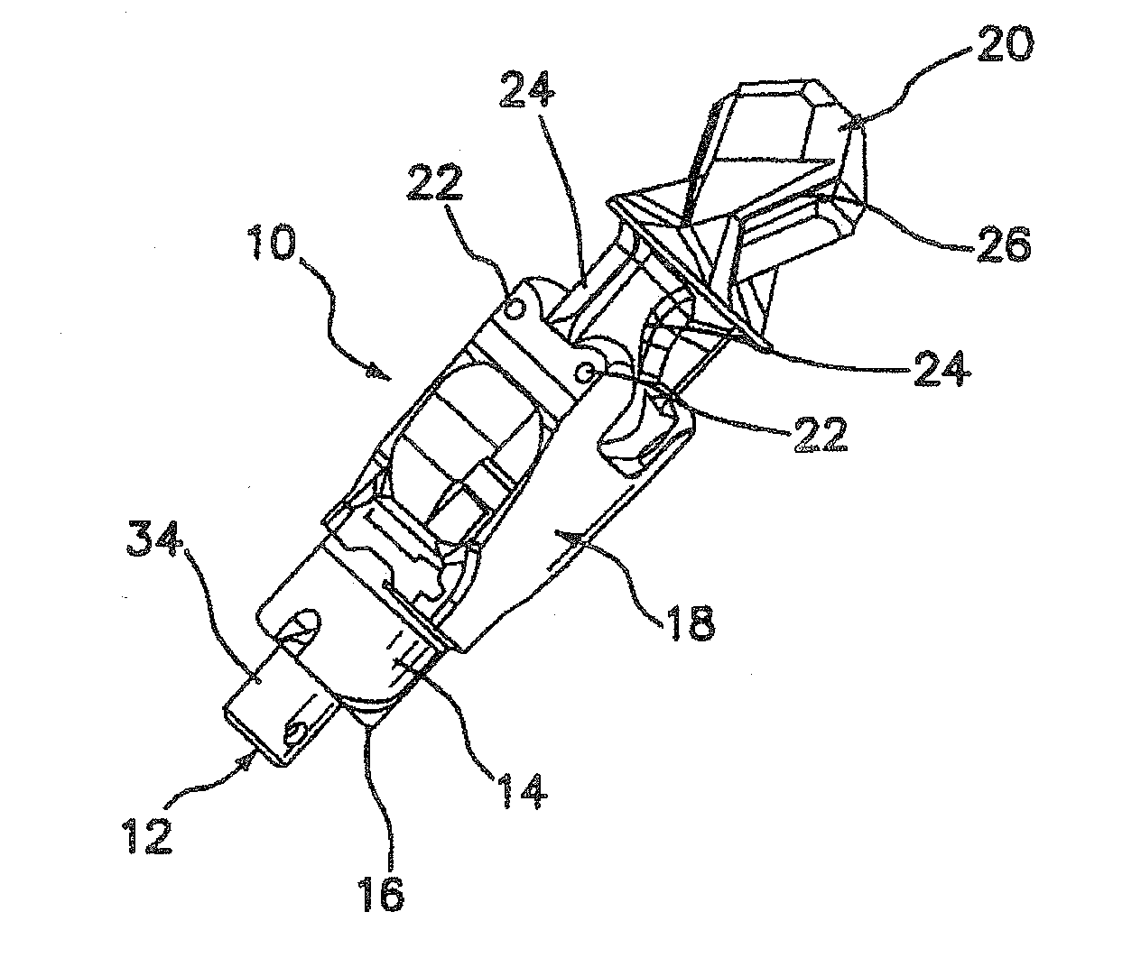
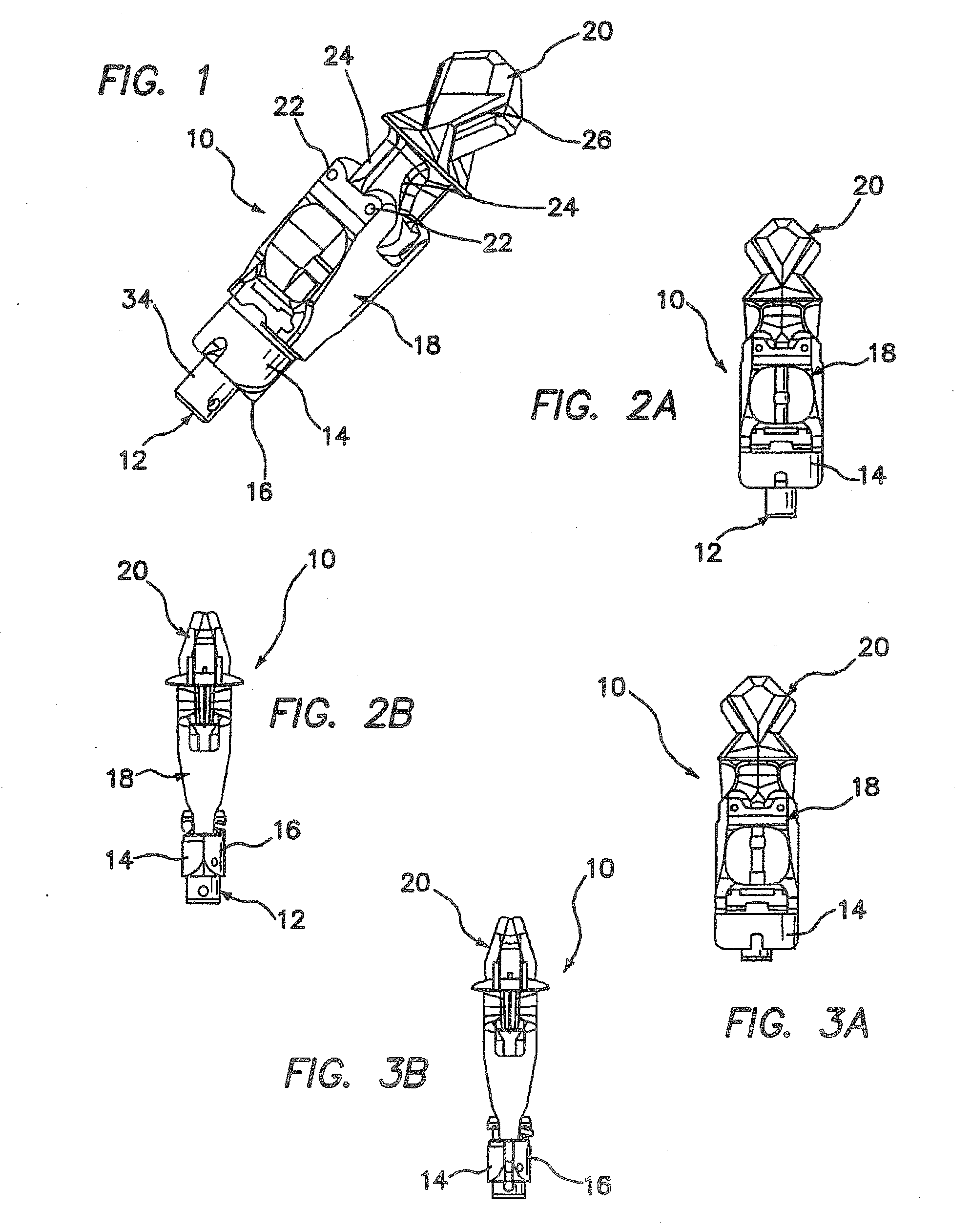
[0104]In FIGS. 18-21 there is shown another implant embodiment 110, wherein like elements are identified with like reference numerals as for the embodiment of FIGS. 1-14, preceded by the numeral 1. As shown, the deployment screw 112 protrudes through the compression pads 114 and 116, which are each integrated into the body 118. The deployment screw 112 is threaded at its distal end into the wedge 120. Two pins 122 attach a pair of arms 124 to the body 118, as shown.
[0105]As noted above, in this embodiment the compression pads 114, 116 are integrated into the body 118. This feature permits the use of a shorter implant than is the case for the implant of FIG. 1. A track 126 in the wedge 120 attaches to track posts 128 on the arms 124 (FIG. 29), which keep the wedge 120 from rotating during deployment. The compression pads expand as the implant is deployed. In particular, the screw 112 expands the pads 114, 116 outwardly by sliding on a compression taper 72 (FIG. 27), as shown in FIGS....
embodiment 210
[0113]Still another embodiment of the inventive implant is illustrated in FIGS. 33-54, wherein like elements to those of the prior embodiments are identified by like reference numerals, preceded by the numeral 2. This embodiment 210 utilizes the cortical bone for fixation in combination with tendon-to-bone compression. In this version of the invention, the deployment screw 212 is offset to one side of the implant 210, for the purpose of permitting easier passing of tendon through the orifice. This implant deploys in two steps. The deployment screw 212 is rotated clockwise as an arm 78 and wedge 220 slide together across tapered faces 80 (FIG. 46) and 82 (FIG. 48) until they lock together with their respective cortical locks 84, 86. The wedge 220 and the arm 78 lock into place by filling a majority of the cross section of the femoral tunnel. Thus, the implant is free to move in the femoral tunnel, allowing tactile feedback to ensure engagement of a cortical tab 88 with the cortex.
[01...
PUM
 Abstract
Description
Claims
Application Information
 - R&D
- Intellectual Property
- Life Sciences
- Materials
- Tech Scout
- Unparalleled Data Quality
- Higher Quality Content
- 60% Fewer Hallucinations
Browse by: Latest US Patents, China's latest patents, Technical Efficacy Thesaurus, Application Domain, Technology Topic, Popular Technical Reports.
© 2025 PatSnap. All rights reserved.Legal|Privacy policy|Modern Slavery Act Transparency Statement|Sitemap|About US| Contact US: help@patsnap.com


