Method and device for detecting a tank level

a technology for detecting the fuel level of the tank, which is applied in the direction of machines/engines, electrical control, instruments, etc., can solve the problems of affecting the accuracy and reliability of the tank level sensor, and increasing the corrosion problem without additional constructive measures

Active Publication Date: 2010-07-22
ROBERT BOSCH GMBH
View PDF19 Cites 37 Cited by
  • Summary
  • Abstract
  • Description
  • Claims
  • Application Information

AI Technical Summary

Benefits of technology

[0010]It is therefore an object of the present invention to provide a more accurate, more reliable method for tank level detection, in which, by using co

Problems solved by technology

While this arrangement is technically simple and cost-effective to implement, it has the disadvantage that the lever usually has an upper dead-center position, as shown in FIG. 1, above which the tank level sensor signal UTSG—max does not change any more, even in the case of a rising tank level, and a lower dead-center position, below which the tank level sensor signal UTSG—min does not change any more, even in the case of a falling tank level.
Consequently, there is an upper and a lower dead volume that cannot be detected, since the mechanical lever is at an end stop before this volume is reached.
Furthermore, deposits due to corrosion on the potentiometer path impair the accuracy and

Method used


Image

  • Method and device for detecting a tank level
  • Method and device for detecting a tank level
  • Method and device for detecting a tank level

Examples


Embodiment Construction

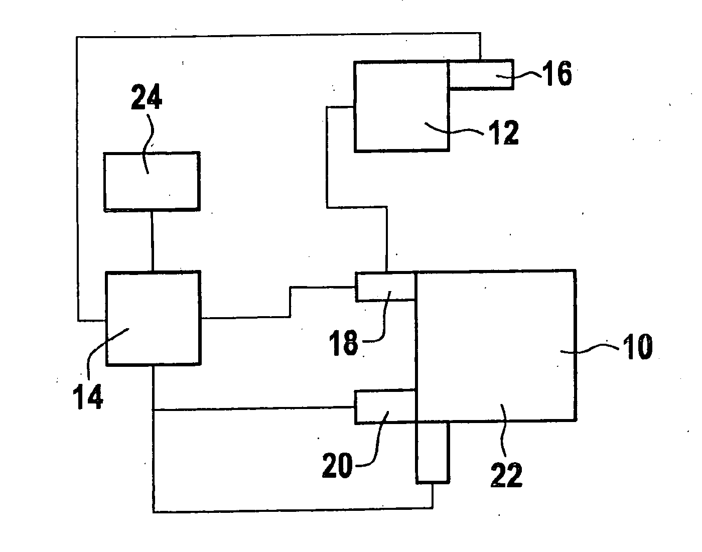
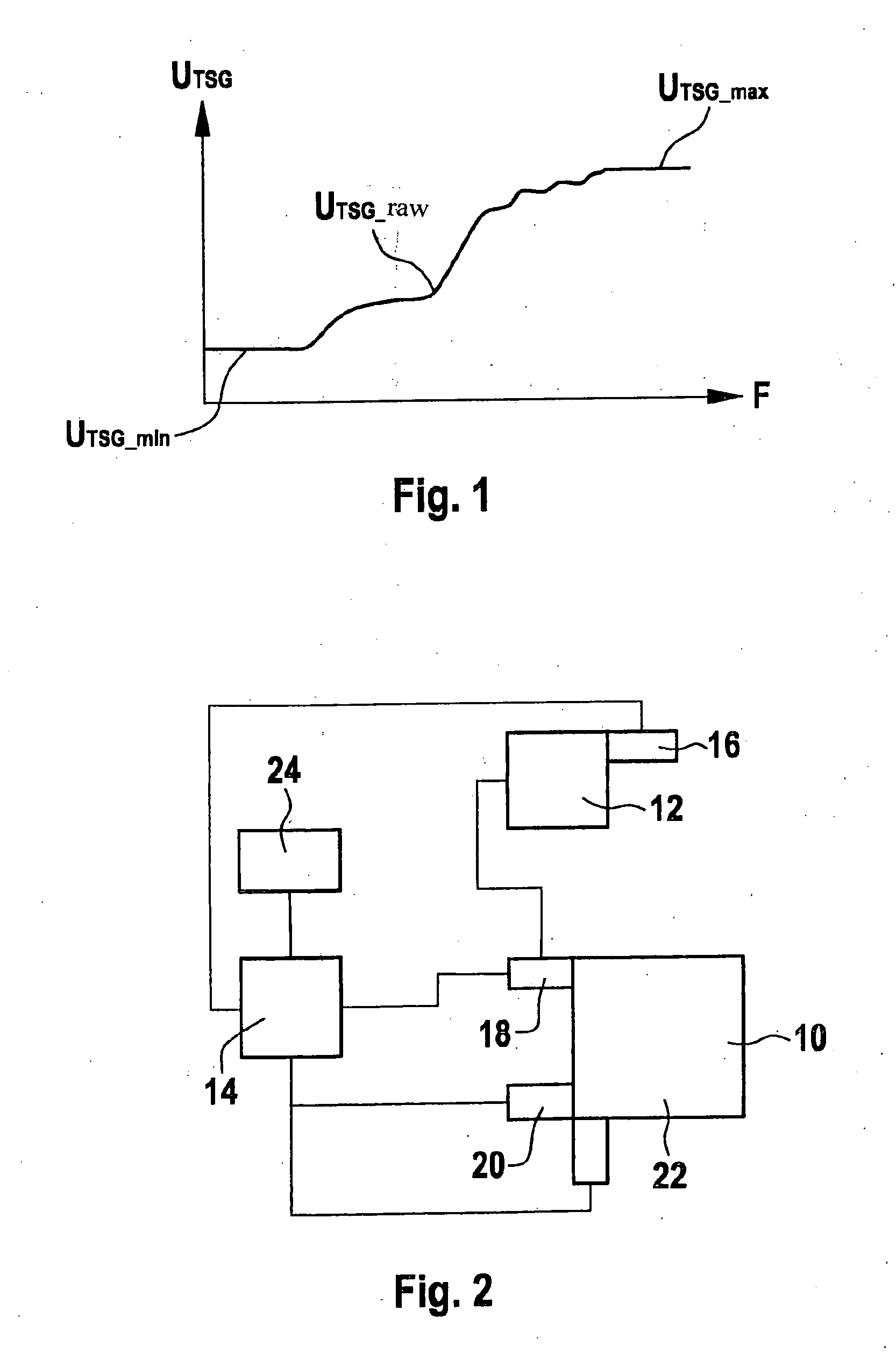
[0029]As shown schematically in FIG. 2, an engine 10 is connected to an engine control unit 14 in such a way that various engine components, such as fuel injectors 18, intake manifolds 20 and a lambda probe 22 are monitored and controlled by engine control unit 14. Furthermore, a fuel tank 12 has a tank level sensor 16, which is developed, for instance, as a usual potentiometer device having a float and a lever, and which emits a voltage signal UTSG to engine control unit 14 that is a function of the tank level.

[0030]In addition, there are further sensors 24 connected to engine control unit 14, for instance, for measuring the engine temperature, the acceleration and the travel speed of the motor vehicle and the like.

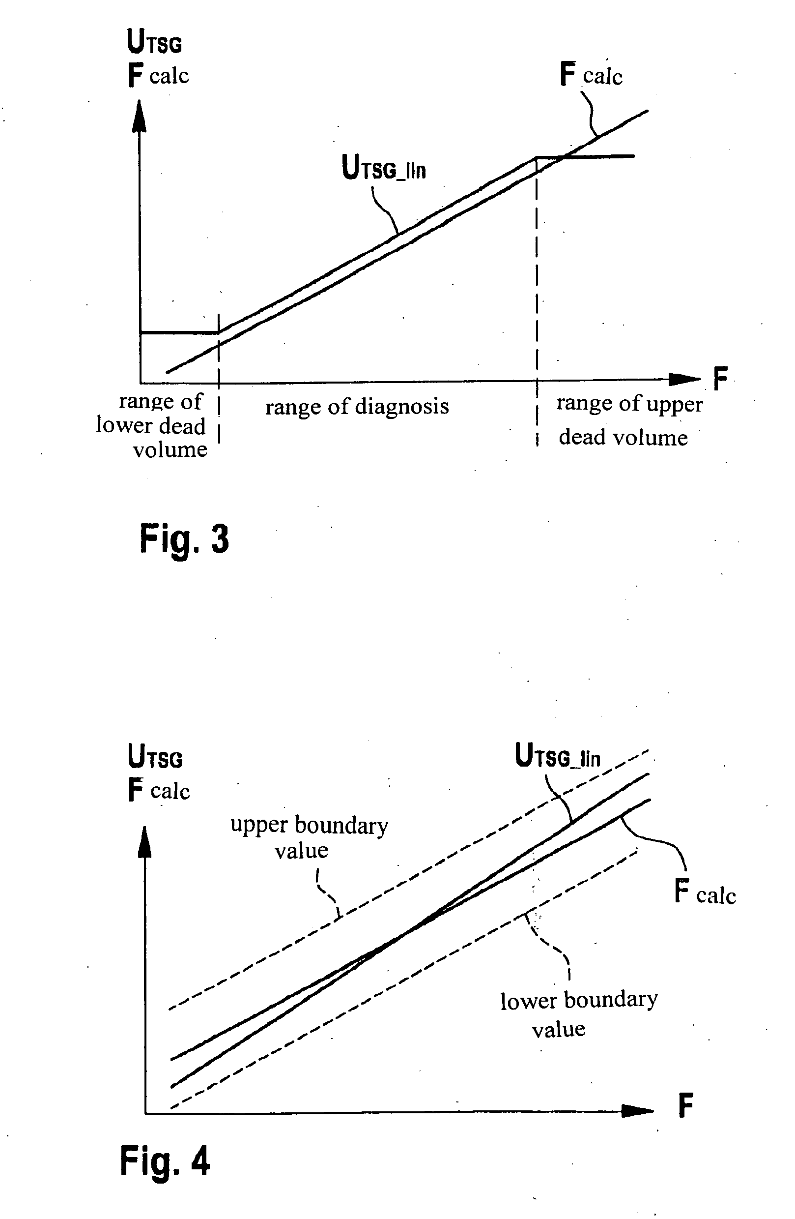
[0031]The signal UTSG emitted by tank level sensor 16 is smoothed by suitable filters and is linearized (UTSG—lin), as shown in FIG. 3. Artifacts caused, for instance, by sloshing of the gasoline in the tank, can be removed by low-pass filtering, in this connection. Furt...


PUM


Abstract

A method for detecting the tank fuel level of a motor vehicle includes: ascertaining the tank level sensor signal (UTSG) of a tank level sensor, determining a calculated tank level (Fcalc) as a function of a fuel quantity consumed by the internal combustion engine, and providing a corrected tank level signal as a function of the tank level sensor signal (UTSG) and the calculated tank level (Fcalc).

Description

BACKGROUND OF THE INVENTION[0001]1. Field of the Invention[0002]The present invention relates to a method and a device for detecting the tank fuel level of a motor vehicle.[0003]2. Description of Related Art[0004]Usually, for detecting a tank fuel level, a tank level sensor makes available a voltage signal as a function of the filling level, which is then evaluated by an instrument cluster, so that a driver may then be provided with a tank level display. Moreover, it is usual that a refueling process is also recorded with the aid of a tank fuel level sensor, by having an increase in the tank level by more than a predetermined boundary value evaluated as a sign of refueling. The tank level sensor is usually based on a potentiometer device, having a lever arm and a float gauge, in this context.[0005]While this arrangement is technically simple and cost-effective to implement, it has the disadvantage that the lever usually has an upper dead-center position, as shown in FIG. 1, above wh...

Claims


Application Information

Patent Timeline
IPC IPC(8): G06F7/00G01M15/04F02D45/00G01F23/00
CPCG01F23/0076G01F23/804
Inventor WINDBERGS, THORPOSSELT, ANDREASLORENZ, MARKO
Owner ROBERT BOSCH GMBH
Why Eureka
Try Eureka