System and method for rapidly heating and cooling a mold

a rapid heating and cooling and mold technology, applied in the direction of auxillary shaping apparatus, manufacturing tools, ceramic shaping apparatus, etc., can solve the problems of limiting the use of constant-temperature injection molding, affecting the final product quality, etc., to achieve facilitate the controlled rapid heating and cooling of the mold

Active Publication Date: 2010-07-29
BRIGHT MASCH INC
View PDF30 Cites 14 Cited by
  • Summary
  • Abstract
  • Description
  • Claims
  • Application Information

AI Technical Summary

Benefits of technology

[0012]The present invention overcomes the problems associated with the prior art by providing a self-contained, portable mold temperature control unit. The invention facilitates the controlled rapid heating and cooling of a mold during each cycle of

Problems solved by technology

There are several well known problems that limit the use of constant-temperature injection molding.
For example, the surface finish and structural integrity of the final part is substantially compromised when a known problem called “premature freezing” occurs.
This is particularly undesirable when molding long and thin parts, optical parts, and parts that require a glossy surface finish.
Further, uneven solidification is another known problem that can result from premature freezing or when the molten plastic is cooled to slowly.
Of course, if this occurs, the final part will likely include several defects (e.g., dimensional distortion, knit lines, poor surface finish, etc.).
For example, the initial cost and development of such facilities is very high.
As another example, daily production costs in current facilities are also high.
Much of these

Method used


Image

  • System and method for rapidly heating and cooling a mold
  • System and method for rapidly heating and cooling a mold
  • System and method for rapidly heating and cooling a mold

Examples


Embodiment Construction

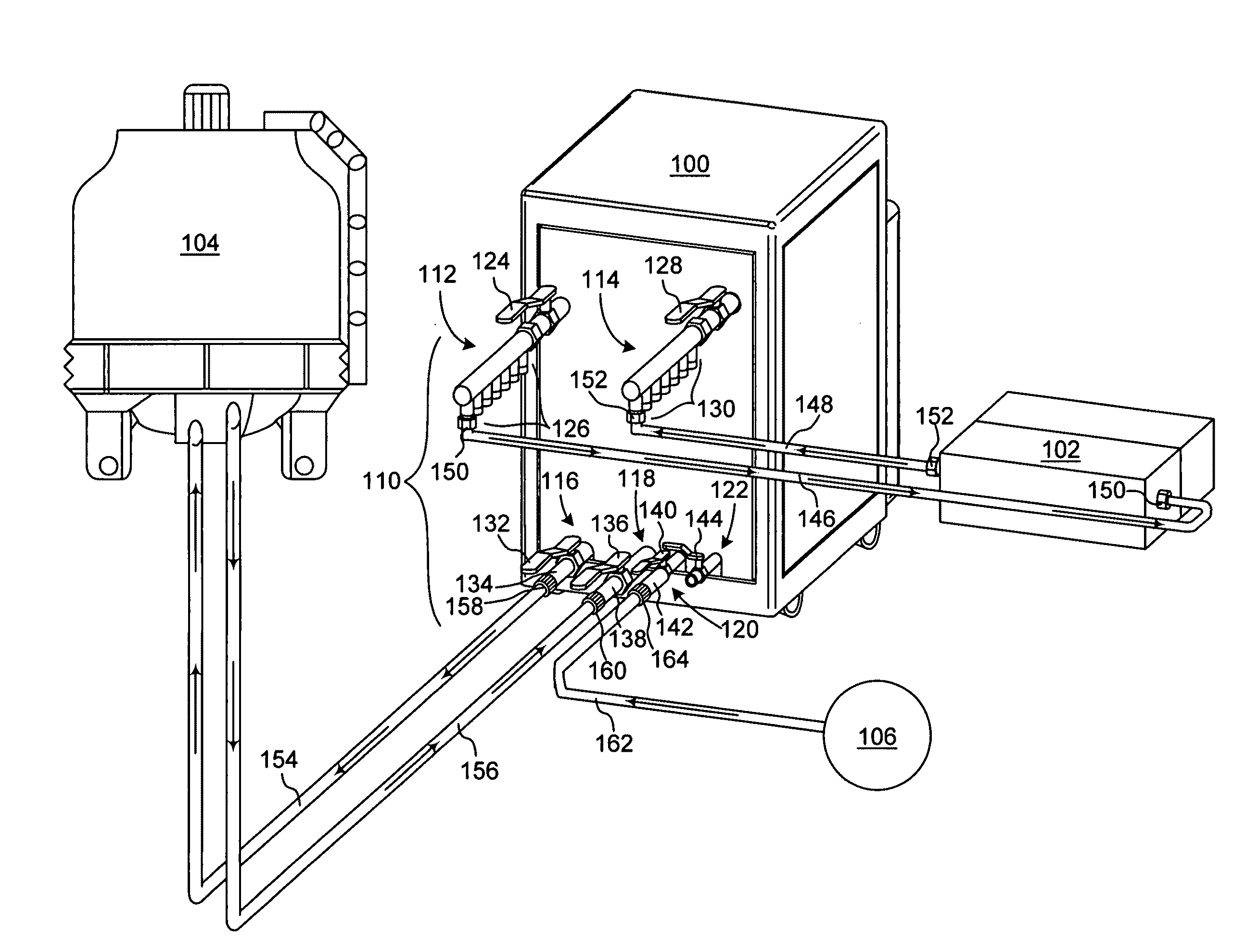
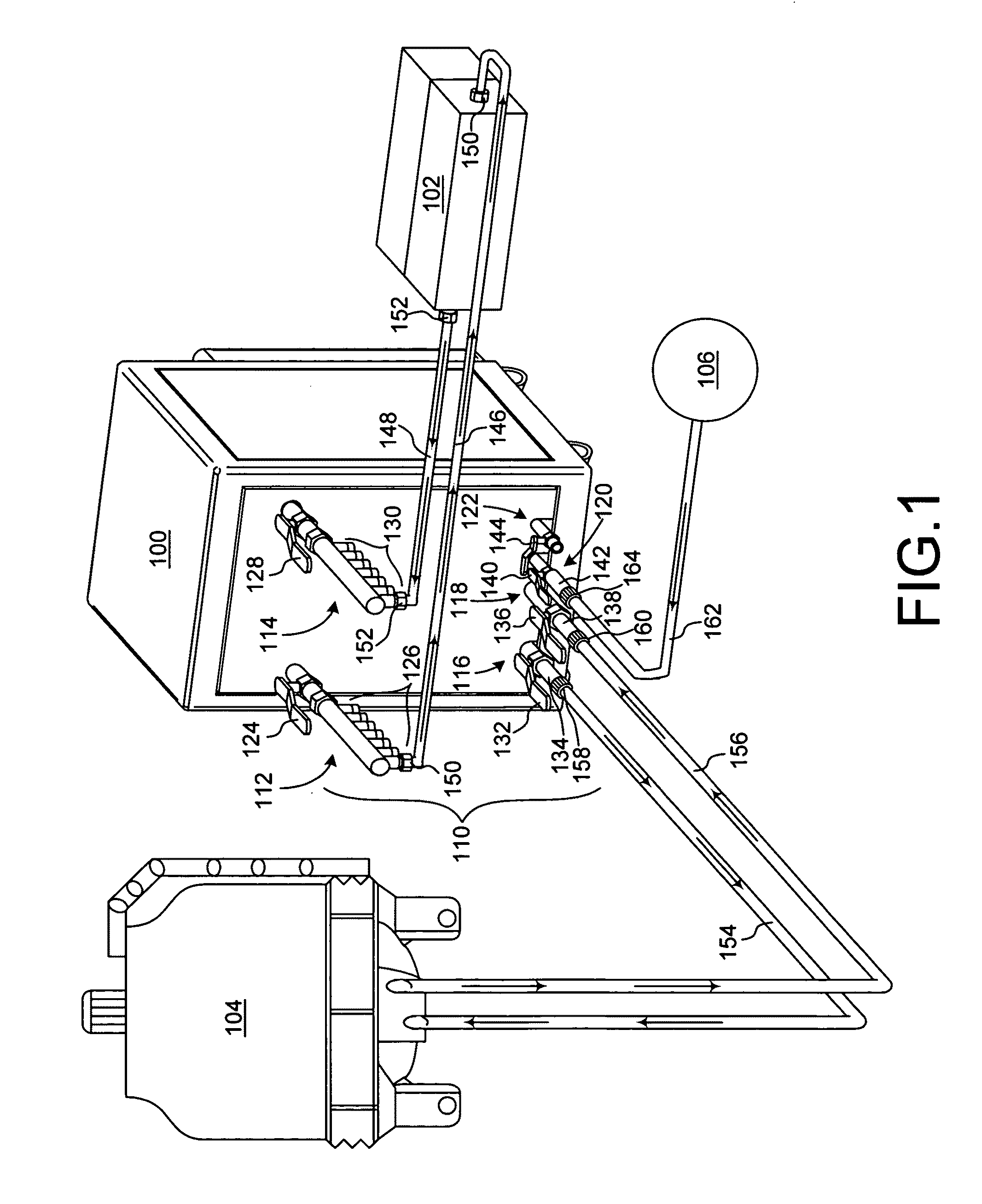
[0037]The present invention overcomes the problems associated with the prior art, by providing a portable mold-temperature control unit that can operate with or without being connected a remote fluid source. In the following description, numerous specific details are set forth (e.g., remote cooling tower, fluid valves, fluid-lines, fluid-line connectors, etc.) in order to provide a thorough understanding of the invention. Those skilled in the art will recognize, however, that the invention may be practiced apart from these specific details. In other instances, details of well known molding practices (e.g., heating / injection / packing, part ejection, plastic type, etc.) and components have been omitted, so as not to unnecessarily obscure the present invention. It should be noted that the term “fluid” is used herein to broadly describe both liquids and / or gasses.

[0038]FIG. 1 shows a perspective view of a portable mold-temperature control unit 100 coupled to a mold 102, a remote fluid so...


PUM

PropertyMeasurementUnit
Temperatureaaaaaaaaaa
Pressureaaaaaaaaaa

Abstract

A portable mold-temperature control unit includes a local heating system, a first fluid duct, a second fluid duct, and a fluid exchange system. The local heating system includes a local heater for heating fluid that is used to rapidly heat a mold. The first fluid duct carries hot fluid heated by the local heating system. The second fluid duct carries cool fluid that is used to rapidly cool a mold. The fluid exchange system includes an outlet that permits fluid to flow from the first and second fluid ducts to the mold during heating and cooling, respectively. The fluid exchange system also includes an inlet that receives the fluid as it returns from the mold. In one embodiment, the heating system reheats the fluid returning from the mold and reuses it to heat the mold again. In a more particular embodiment, the heating system includes a steam generator that generates steam used to heat the mold. In another embodiment, the portable mold-temperature control system includes a local cooling system that cools the fluid used to cool the mold. In a more particular embodiment, the local cooling system cools fluid returning from the mold and reuses it to cool the mold. A method for using the portable mold-temperature control unit is also disclosed.

Description

RELATED APPLICATIONS[0001]This application claims the benefit of co-pending U.S. Provisional Patent Application No. 61 / 274,048, filed Aug. 12, 2009 by the same inventors, which is incorporated herein by reference in its entirety. This application also claims the benefit of foreign priority to Chinese Application No. 200820202111.0, filed Oct. 16, 2008 by at least one common inventor, which is also incorporated herein by reference in its entirety.BACKGROUND OF THE INVENTION[0002]1. Field of the Invention[0003]This invention relates generally to heat exchange systems, and more particularly to a method and device for controlling the temperature of molds. Even more particularly, the invention relates to a device and method for rapidly heating and cooling a mold during a molding process.[0004]2. Description of the Background Art[0005]In the manufacturing industry, injection molding is a common process for producing parts. Conventional injection molding requires the use of a constant-temp...

Claims


Application Information

Patent Timeline
IPC IPC(8): B29C33/04
CPCB29C35/007B29C45/7306B29C35/049B29C45/78
Inventor WANG, ZHONGHILL, CHARLES R.
Owner BRIGHT MASCH INC
Why Eureka
Try Eureka