Heat dissipating device and method of manufacturing the same

Inactive Publication Date: 2010-07-29
BEIJING AVC TECH RES CENT
View PDF20 Cites 27 Cited by
  • Summary
  • Abstract
  • Description
  • Claims
  • Application Information

AI Technical Summary

Benefits of technology

[0007]To overcome the disadvantages in the conventional loop heat pipe, a primary object of the present invention is to provide a heat dissipating device and a method of manufacturing the same, so that the heat dissipating device can (1) fully contact with a heat producing electronic chip to efficiently dissipate heat produced by the electronic chip; (2) largely reduce the thermal resistance during heat dissipation; and (3) have an evaporator that occupies only a small space to facili

Problems solved by technology

While these ways, are more or less helpful in solving the problem of heat dissipation, for the high-power electronic devices, they still have some disadvantages.
As a result, noise produced during the operation of the cooling fan is increased at the same time, and the heat dissipating device would become bulky and heavy to not only cause problem in installation thereof but also apply great pressure on the electronic devices; (2) in the case of employing cooling fans, heat pipes and heat sinks to dissipate heat, while the disadvantages in the first way are overcome, the heat dissipating device itself becomes very complicated in structure, the design and installation of heat pipes are frequently subject to practical structural restriction, and the heat dissipating ability is still limited if the number, of heat pipes is low; and (3) in the case of employing liquid cooling techniques to dissipate heat, while the liquid cooling is superior to the above two ways in terms of the heat dissipating performance thereof and therefore has high potential in heat dissipation technical field, the liquid cooling involves extremely complicated mechanisms and requires v

Method used


Image

  • Heat dissipating device and method of manufacturing the same
  • Heat dissipating device and method of manufacturing the same
  • Heat dissipating device and method of manufacturing the same

Examples


Example

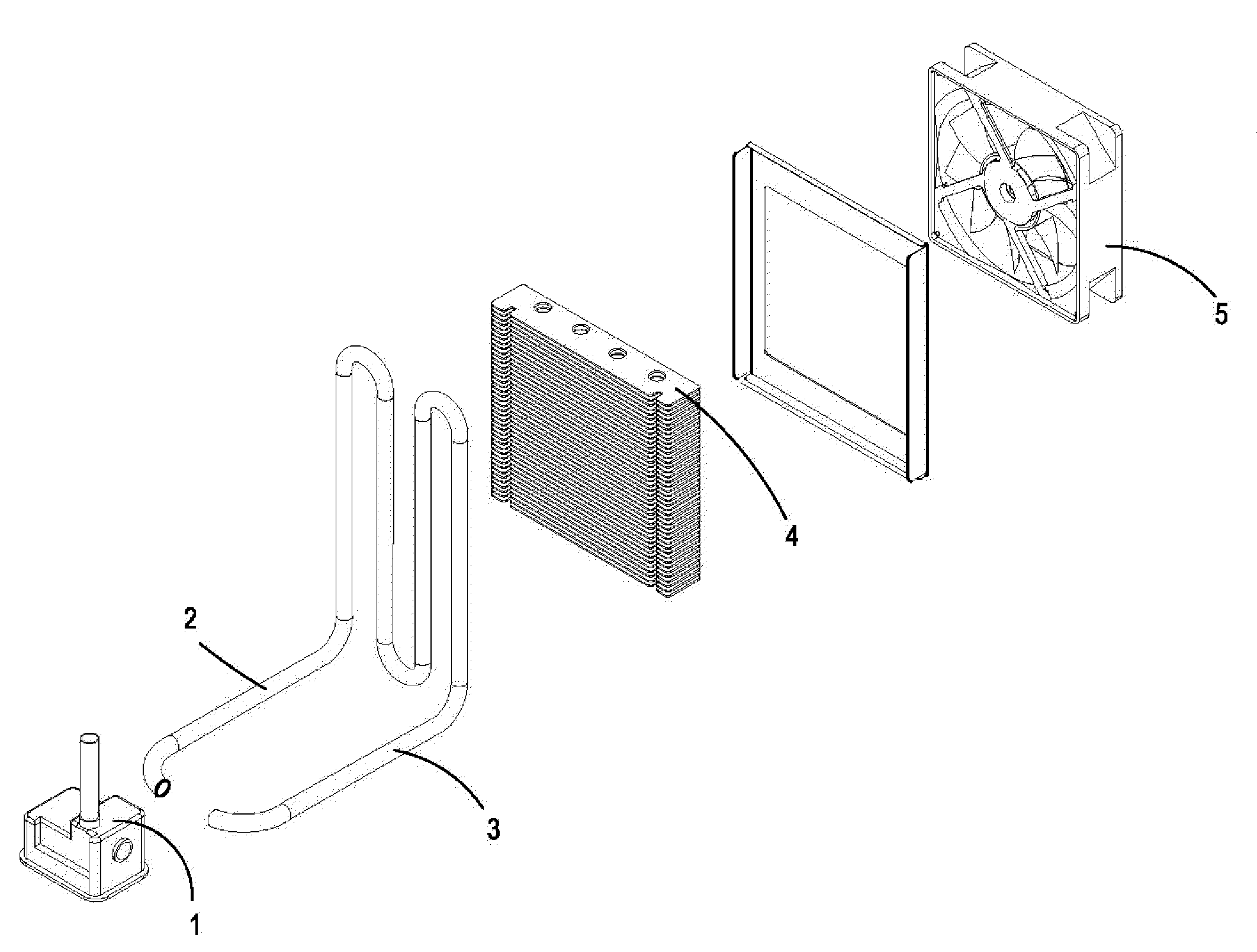
[0044]Please refer to FIGS. 2 and 8 that assembled and exploded perspective views, respectively, of a heat dissipating device according to a preferred embodiment of the present invention characterized by having a loop heat pipe with flat evaporator. As shown, the heat dissipating device of the present invention mainly includes a fiat evaporator 1, a vapor pipe 2, a liquid pipe 3, and a condenser 4. A cooling fan 5 can be further mounted to one side face of the condenser 4 for forcing air through the condenser 4. The flat evaporator 1 can have a rectangular shape, a polygonal shape, or any other geometrical shape.

[0045]Please refer to FIGS. 3A, 3B, and 7. The flat evaporator 1 includes a main body consisting of a bottom plate 11, a porous material 12, and a top lid 13. The porous material 12 is located in a receiving space defined between the bottom plate 11 and the top lid 13 of the main body. The main body is provided at two opposite sides with a port each, namely, a vapor port 131...


PUM

PropertyMeasurementUnit
Temperatureaaaaaaaaaa
Poweraaaaaaaaaa
Shapeaaaaaaaaaa

Abstract

A heat dissipating device includes a flat evaporator, a vapor pipe, a liquid pipe, and a condenser. The flat evaporator consists of a bottom plate, a porous material, and a top lid. The porous material is located on the bottom plate and provided with vapor flow passages. The vapor pipe and liquid pipe are communicably connected at respective one end to a vapor port and a liquid port on the evaporator, and at the other end to two sides of the condenser. The evaporator has simple structure and low manufacturing cost, and can fully effectively bear on an electronic chip to enable reduced room needed for installing the evaporator and reduced thermal resistance during heat dissipation. The heat dissipating device can be used to dissipate heat produced by computer chips, and to cool LED illuminating devices, chips for communication devices, high-power heat-producing elements in military, medical, aerial, and aerospace apparatuses.

Description

FIELD OF THE INVENTION[0001]The present invention relates to a heat dissipating device applicable to elect conic products, and more particularly to a heat dissipating device having a loop heat pipe and to a method of manufacturing the heat dissipating device.BACKGROUND OF THE INVENTION[0002]Cooling of high-power electronic chips is a very, important technical aspect in connection with the operation of different electronic, computing, communication, and photo-electric apparatuses. The following are several ways being currently-adopted in the market for dissipating heat produced by high-power electronic devices: (1) employing cooling fans and heat sinks; (2) employing cooling fans, heat pipes and heat sinks; and (3) employing cooling fans and liquid-cooling technology. While these ways, are more or less helpful in solving the problem of heat dissipation, for the high-power electronic devices, they still have some disadvantages. For example, (1) in the case of employing fans and heat s...

Claims


Application Information

Patent Timeline
IPC IPC(8): H05K7/20F28D15/02B21D53/02
CPCF28D15/0266F28D15/046H01L23/427Y10T29/49353H01L2924/0002H01L23/467H01L2924/00
Inventor LI, JI
Owner BEIJING AVC TECH RES CENT
Why Eureka
Try Eureka