Composite cement panel

a technology of composite cement and cement slurry, applied in the field of composite cement panels, can solve the problems of time delay, mixing, handling and/or applying concrete slurry on site, and laborious

Inactive Publication Date: 2010-07-29
LIM CO LTD
View PDF54 Cites 23 Cited by
  • Summary
  • Abstract
  • Description
  • Claims
  • Application Information

AI Technical Summary

Problems solved by technology

Construction 100 suffers from a range of problems.
A further problem is that on site cladding construction makes quality control difficult, can cause damage to the waterproofing system, and is subject to the vagaries of inclement weather during construction leading to time delay.
In addition, mixing, handling and / or applying concrete slurry on site can be messy and laborious.

Method used


Image

  • Composite cement panel
  • Composite cement panel
  • Composite cement panel

Examples


Embodiment Construction

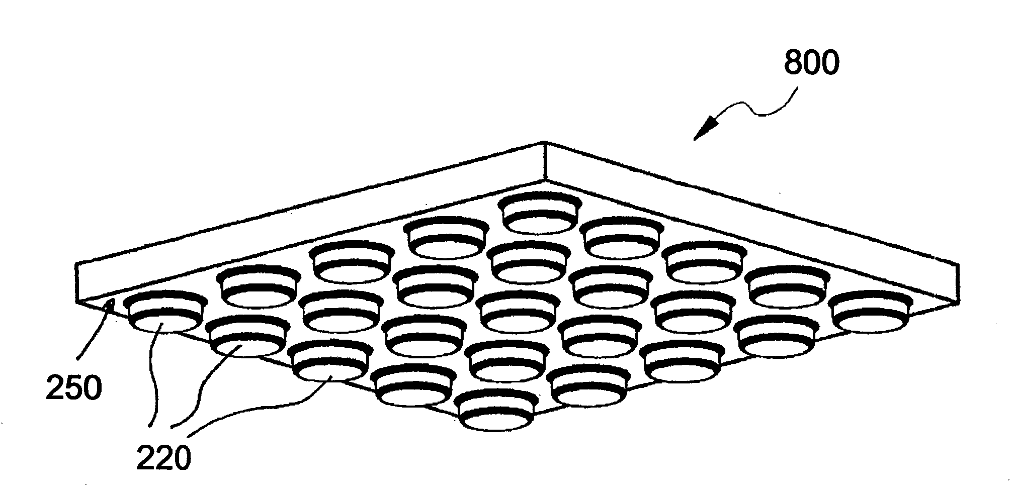
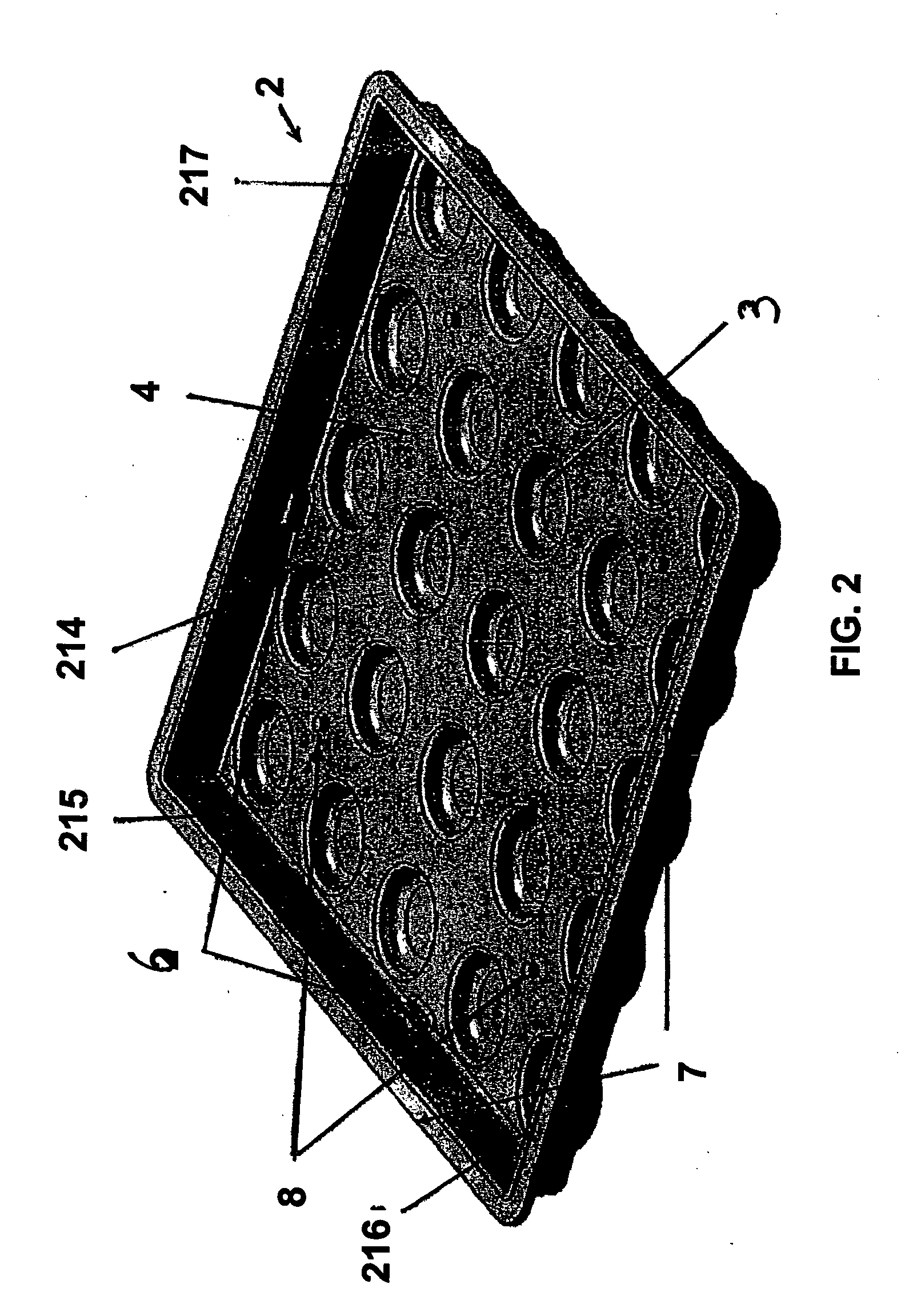
[0020]FIG. 2 shows a formwork 2, made of metal for example, for casting a composite cement panel 800 shown in FIG. 7A. Formwork 2 has an array of recesses 3 formed on the base surface 4. Recesses 3 are positioned spaced apart from each other across the base surface 4 of the formwork 2. Guide abutments 6 are provided on two adjacent inner surfaces 214, 215 of the metal formwork 2. Formwork 2 further includes pins 8 positioned on the bottom surface 4. Pins 8 extend upwardly from the base surface 4 of formwork 2. Formwork 2 ends with an upturn skirting 7 along the peripheral edge, allowing ease of handling the formwork 2 during casting or transportation of the cement panel 800.

[0021]FIG. 3 illustrates a light-weight core material board, such as a foam board 200, placed in formwork 2 before the process of cement casting of the composite cement panel 800. Foam board 200 has through holes 202 formed thereon by, for example, drilling, stamping, cutting, punching or pre-made integratedly du...


PUM

PropertyMeasurementUnit
heightaaaaaaaaaa
thicknessaaaaaaaaaa
thicknessaaaaaaaaaa

Abstract

This invention relates to a composite panel for a rooftop surface having a core material board having a top surface and a bottom surface with a plurality of openings through said core material board extending from said top surface to said bottom surface; a rigid outer shell of solid material that encapsulates said core material board; a plurality of supports of said solid material wherein each of said plurality of supports extends through one of said plurality of openings in said core material board; and a plurality of legs on a portion of said rigid outer shell covering said bottom surface of core board material.

Description

TECHNICAL FIELD[0001]The present invention relates to composite cement panel for use in a roof deck or similar structure, and a fabricating method of the cement panel.BACKGROUND ART[0002]FIG. 1 illustrates a typical construction 100 of a cladding construction system of a concrete roof deck 102. A cement sand base 104 is formed over the roof deck 102, the base 104 being screed to form a slope or slope-to-fall gradient to create a drainage fall into a drain 106 and downpipe 108. A waterproof membrane 110 is laid over the cement sand base 104, interrupted only by downpipe 108, and extending a height 112 of 300 mm up the inside surface of walls 114. Where the deck 102 meets some walls 114, the transition of the waterproof membrane from the horizontal surface to the vertical surface may be effected by use of waterproof filler such as poly foam 116. A thermal insulating layer 118 is constructed on top of the membrane 110, the layer 118 comprising extruded polystyrene insulation board of 5...

Claims


Application Information

Patent Timeline
Patent Type & Authority Applications(United States)
IPC IPC(8): E04D3/35B32B3/26B32B27/06B32B13/12E04C2/288B28B1/00B29C67/24
CPCB28B7/0064B28B23/0068E04D11/00Y10T428/24174E04F15/02Y10T428/24347E04D11/005E04F15/185B28B1/30E04C2/26E04C2/288E04C2/30
Inventor LIM, JEE KENG JAMES
Owner LIM CO LTD
Why Eureka
Try Eureka