
Air battery system and methods for using and controlling air battery system

a battery system and air technology, applied in the direction of secondary cells, cell components, cell component details, etc., can solve the problems of air battery deterioration, air battery drawback, electrolyte tends to evaporate easily, etc., to achieve the effect of increasing the internal resistance of the sealed air battery cell and reliably preventing

Inactive Publication Date: 2010-07-29
TOYOTA JIDOSHA KK
View PDF12 Cites 12 Cited by
  • Summary
  • Abstract
  • Description
  • Claims
  • Application Information

AI Technical Summary

Benefits of technology

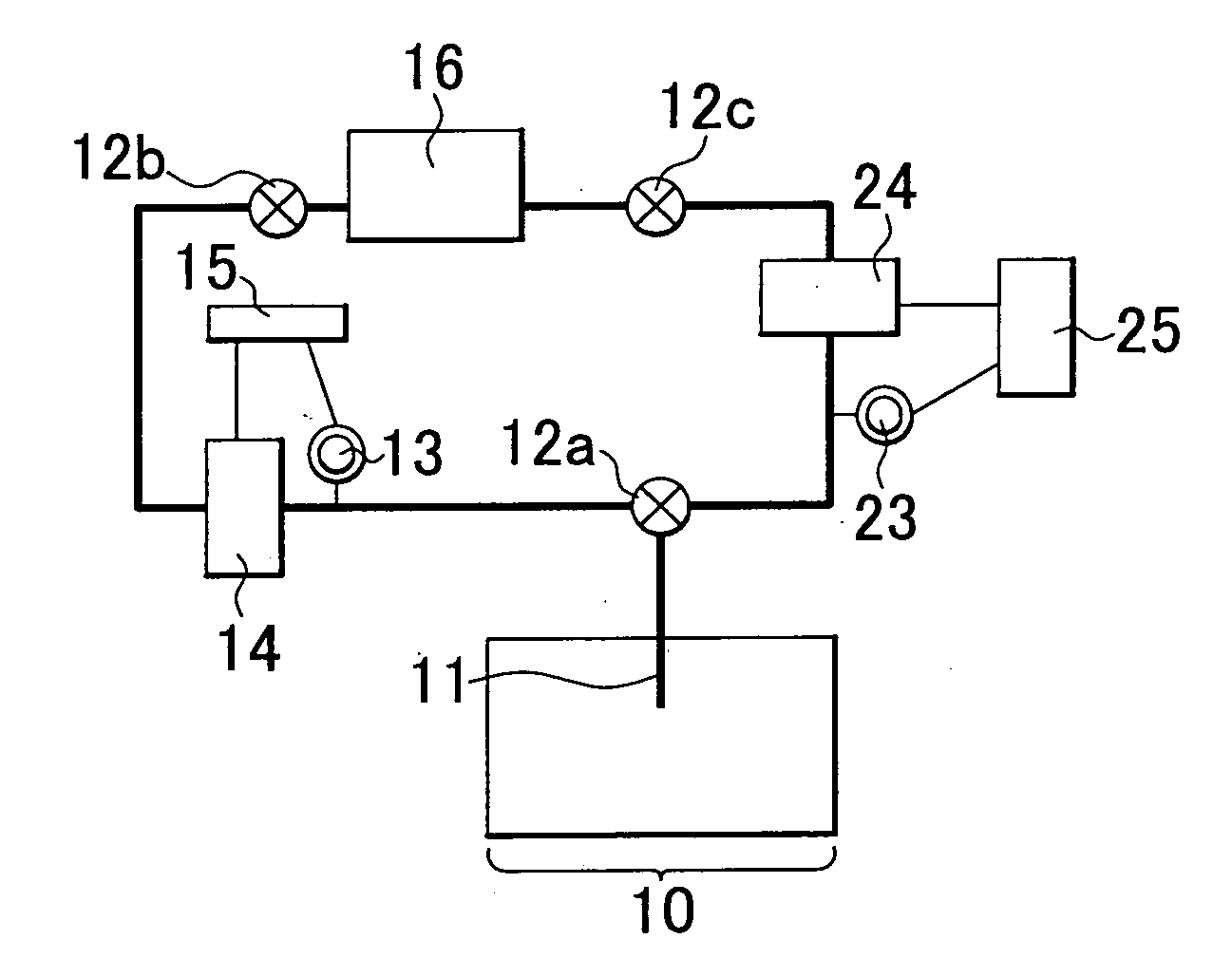
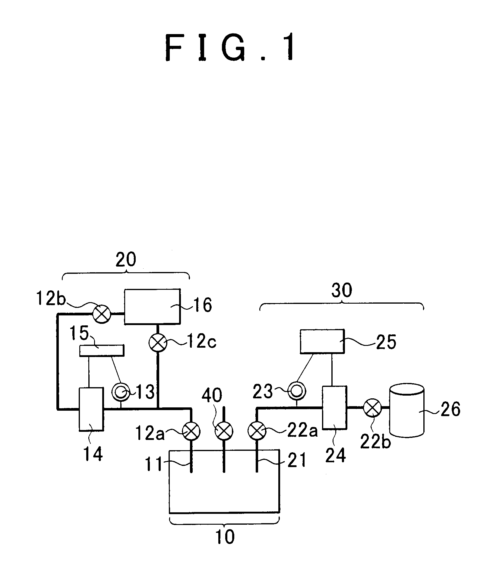
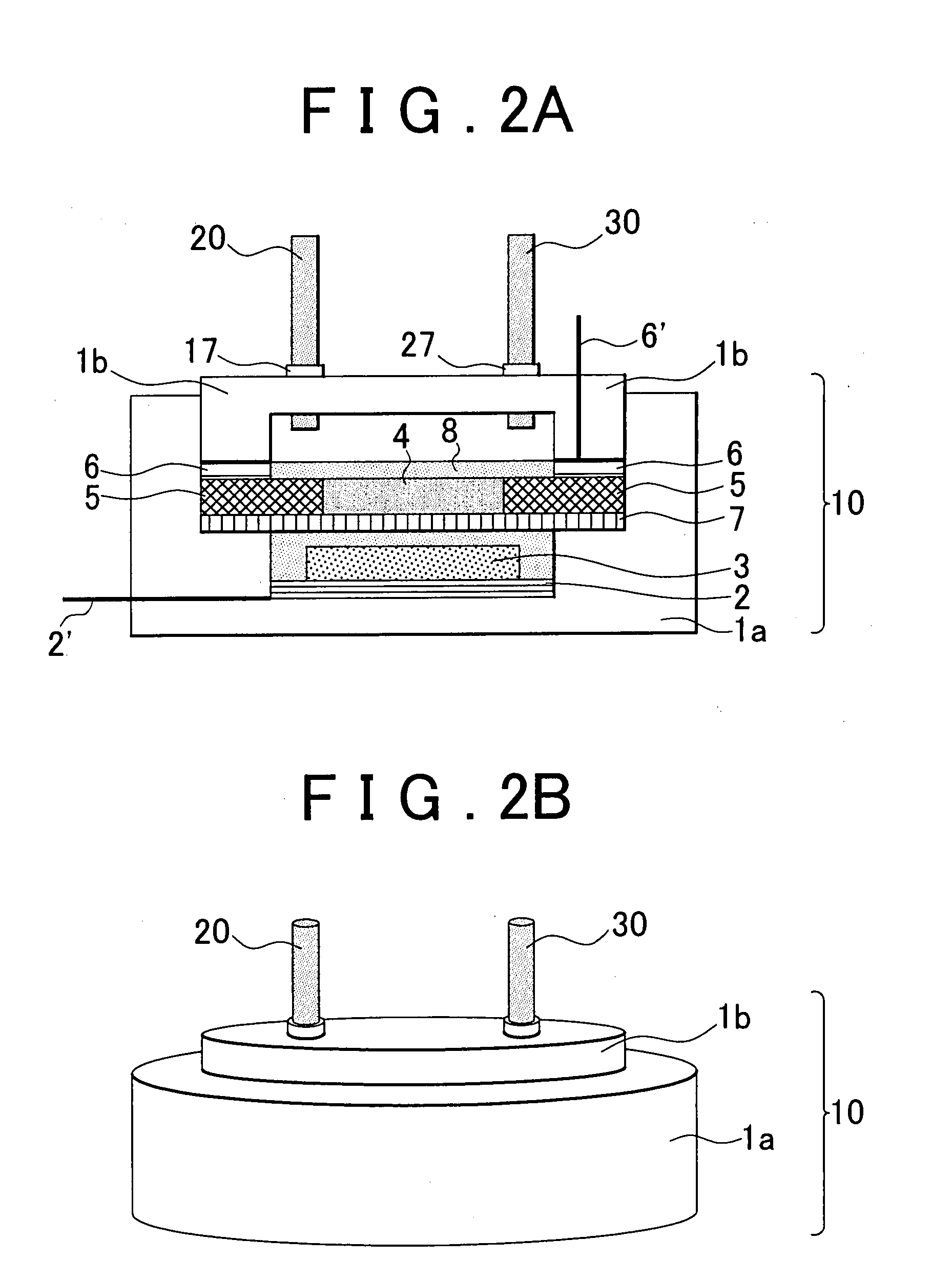
[0010]The first aspect of the invention relates to an air battery system, comprising: (i) a sealed air battery cell having: an air electrode having an air electrode layer containing a conductive material and an air electrode power collector for collecting electric power from the air electrode layer; a negative electrode having a negative electrode layer containing an negative electrode active material that adsorbs and releases metal ions and a negative electrode power collector for collecting electric power from the negative electrode layer; a separator provided between the air electrode layer and the negative electrode layer; and a sealed air battery case; and (ii) a depressurization portion that reduces the internal pressure of the sealed air battery cell to below the atmospheric pressure.
[0011]According to the air battery system of the first aspect of the invention, due to the depressurization portion, the air battery system can be charged with electric power in a depressurized state. Charging the air battery in a depressurized state reduces the concentration of oxygen dissolved in the electrolyte solution and reduces the oxygen partial pressure in the sealed air battery cell, thus achieving a high power charge efficiency.
[0013]In this case, further, the air battery system may also have a gas feedback portion that returns the drawn gas to the sealed air battery cell. According to this structure, a high power charge efficiency can be achieved by reducing the internal pressure of the sealed air battery cell upon power charge, and a high power discharge efficiency can be achieved by boosting the internal pressure of the sealed air battery cell up to the original level upon power discharge.
[0016]In the above-described air battery system, an electrolyte solution may be provided in the sealed air battery cell such that the air electrode layer and the negative electrode layer are always filled with the electrolyte solution regardless of a change in the volume of the air electrode and a change in the volume of the negative electrode. In this case, a shortage of the electrolyte solution, which may cause an increase in the internal resistance of the sealed air battery cell, can be reliably prevented.
[0021]The second aspect of the invention relates to a method for using an air battery system. This method includes: reducing the internal pressure of the sealed air battery cell when the air battery system is charged with electric power; and boosting the internal pressure of the sealed air battery cell when electric power is discharged from the air battery system.
[0023]As such, the invention provides air battery systems that can prevent the moisture in air from entering the air battery and thus achieves a high power discharge efficiency, etc.

Problems solved by technology

However, in the case of such open-type air batteries, the moisture in the air is also drawn into the air battery together with oxygen, and it deteriorates the air battery.
Further, open-type air batteries have a drawback that electrolyte tends to evaporate easily.
According to this battery, because the battery is sealed, the moisture in the air does not enter the battery, which enhances the storability of the battery and prolongs the cycle life of the battery.
However, such sealed oxygen lithium secondary batteries have the following drawbacks.

Method used


Image

  • Air battery system and methods for using and controlling air battery system
  • Air battery system and methods for using and controlling air battery system
  • Air battery system and methods for using and controlling air battery system

Examples


Embodiment Construction

[0032]Hereinafter, air battery systems and methods for using air battery systems according to example embodiments of the invention will be described in detail.

[0033]First, an air battery system according to an example embodiment of the invention will be described. This air battery system is constituted of a sealed air battery cell and a depressurization portion. The sealed air battery cell has an air electrode, a negative electrode, and a separator provided between the air electrode and the negative electrode. The air electrode has an air electrode layer containing a conductive material and an air electrode power collector for collecting electric power from the air electrode layer, and the negative electrode has a negative electrode layer that adsorbs and releases metal ions and a negative electrode power collector for collecting electric power from the negative electrode layer. The depressurization portion is operable to reduce the internal pressure of the sealed air battery cell d...


PUM


Abstract

An air battery system has a sealed air battery cell (10) having: an air electrode having an air electrode layer (4) containing a conductive material and an air electrode power collector (6) for collecting electric power from the air electrode layer; a negative electrode having a negative electrode layer (3) containing an negative electrode active material that adsorbs and releases metal ions and a negative electrode power collector (2) for collecting electric power from the negative electrode layer; a separator (7) provided between the air electrode layer and the negative electrode layer; and a sealed air battery case (1a, 1b). The air battery system also has a depressurization portion (20) that reduces the internal pressure of the sealed air battery cell to below the atmospheric pressure.

Description

FIELD OF THE INVENTION[0001]The invention relates to an air battery system incorporating a sealed air battery cell and methods for using and controlling such an air battery system.BACKGROUND OF THE INVENTION[0002]Air batteries are nonaqueous batteries using air as a positive-electrode active material, and they have a relatively high energy density and are easy to be made small in size and light in weight, which are desirable. When metal Li is used as a negative-electrode active material of such an air battery, the following reactions (1) to (4) occur.[0003]DISCHARGED STATENEGATIVE ELECTRODE: 2Li→2Li++2e−  (1)AIR ELECTRODE: 2Li++2e−+O2→Li2O2   (2)Some Amount of Li2O may be Generated.[0004]CHARGED STATENEGATIVE ELECTRODE: 2Li++2e−→2Li   (3)AIR ELECTRODE: Li2O2→2Li++2e−+O2   (4)[0005]Air batteries are structured to take in oxygen from the outside and thus they usually have porous membranes having a high oxygen permeability. However, in the case of such open-type air batteries, the mois...

Claims


Application Information

Patent Timeline
IPC IPC(8): H01M10/44H01M2/12
CPCH01M8/04089H01M12/02Y02E60/50H01M12/08H01M12/06Y02E60/10
Inventor NAKANISHI, SHINJI
Owner TOYOTA JIDOSHA KK
Learn More