Vehicle Propulsion Device

a propulsion device and vehicle technology, applied in the direction of motor/generator/converter stopper, dynamo-electric converter control, lighting and heating apparatus, etc., can solve the problems of fuel consumption improvement, electric power consumption drop, etc., to reduce the temperature rise reduce the increase of the loss of copper and iron of the motor generator, and charge quickly

Active Publication Date: 2010-07-29
ATSUMITEC CO LTD
View PDF1 Cites 7 Cited by
  • Summary
  • Abstract
  • Description
  • Claims
  • Application Information

AI Technical Summary

Benefits of technology

[0018]In this situation, the storage battery can be more quickly charged since the thermal energy generated by the motor generator is recovered as electric power by using the first thermoelectric conversion element, and then the storage battery is charged by being supplied with the electric power. Furthermore, the temperature rise of the motor generator is diminished by converting the thermal energy of the motor generator into electric power, so that the increase of the copper and iron losses of the motor generator is further alleviated. As a consequence, if the vehicle is a hybrid vehicle, fuel consumption is further improved due to the decrease of discharge rate of the storage battery and the diminishment of temperature rise of the motor generator.
[0019]The vehicle propulsion device may further comprise, for example, a battery temperature sensor t

Problems solved by technology

If the vehicle is a hybrid vehicle, such a decrease in

Method used


Image

  • Vehicle Propulsion Device
  • Vehicle Propulsion Device
  • Vehicle Propulsion Device

Examples


first embodiment

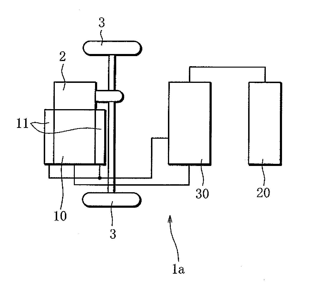
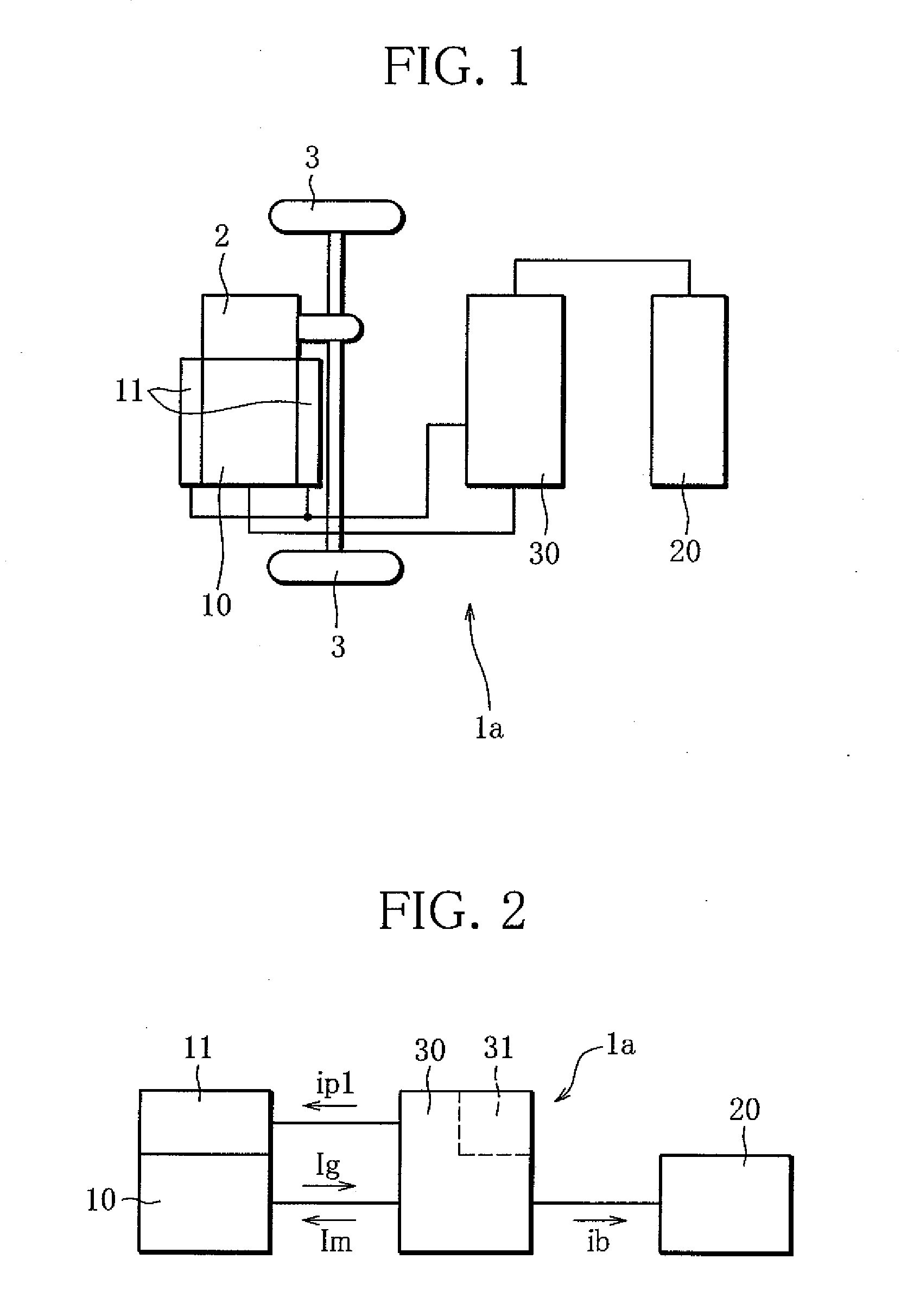
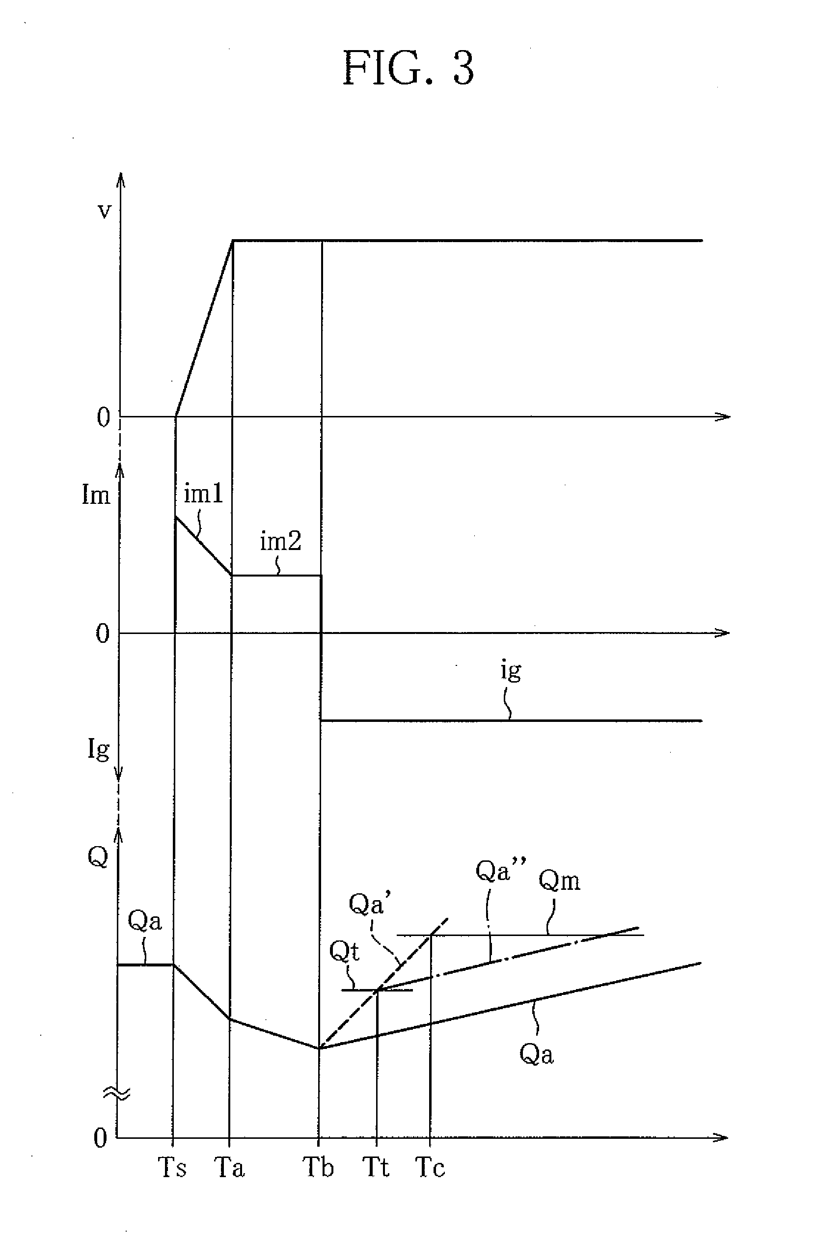
[0029]A vehicle propulsion device la according to the invention will be described below with reference to FIGS. 1 to 3. FIG. 1 is a schematic configuration view showing the propulsion device 1a. FIG. 2 is a block diagram for explaining the operation of the propulsion device 1a. FIG. 3 is a graph showing temporal changes in vehicle speed v, motor generator current, and quantity of electricity Q stored in a battery, when the propulsion device la is in operation.

[0030]The propulsion device la has a motor generator 10, a first thermoelectric conversion element 11 that is thermally connected to the motor generator 10, a battery 20, and a power control unit 30 (hereinafter, referred to as “PCU 30”). The PCU 30 detects an operation condition of a vehicle, and controls the sending and receiving of electric current (or electric power) of the motor generator 10, the first thermoelectric conversion element 11 and the battery 20. A transmission 2 is coupled to an output shaft of the motor gener...

second embodiment

[0055]The temporal change of the quantity of electricity Q in FIG. 8 is shown in comparison with that of the In FIGS. 7 and 8, the electric current of the motor generator 10 is denoted by motor drive current Im in a plus region and by regenerated current Ig in a minus region. FIG. 7 shows current supply directions indicated by arrows. In FIG. 8, the electric current that flows out of a PCU 30 is positive current, whereas the electric current that flows into the PCU 30 is negative current.

[0056]As illustrated in FIG. 6, the propulsion device 1c of the third embodiment is different from the propulsion device 1b of the second embodiment in that the propulsion device 1c has a second thermoelectric conversion element 21 that is thermally connected with the battery 20 and functions as a thermoelectric generation element due to Seebeck effect. The propulsion device 1c is capable of recovering a portion of thermal energy generated by the charge / discharge of the battery 20 by using the seco...


PUM


Abstract

When a drive wheel (3) of a vehicle is driven by a motor generator (10) that operates as a motor, electric power is supplied from a storage battery (20) to the motor generator (10). When the drive wheel (3) is braked by the motor generator (10) that operates as a generator, electric power is supplied from the motor generator (10) to the storage battery (20), and a first thermoelectric conversion element (11) is supplied with electric power from the motor generator (10) to cool the motor generator (10).

Description

TECHNICAL FIELD [0001]The present invention relates to a vehicle propulsion device in which a motor generator is used as a power source independently or in combination with another power source.BACKGROUND ART [0002]An electric car is known as a vehicle in which a motor generator is utilized as a power source. When the electric car is moving or when it is accelerating, the electric power stored in a storage battery (hereinafter, occasionally referred to as a “battery”) is supplied to the motor generator that works as a motor. When the car is braked, the regenerated electric power obtained by operating the motor generator as a generator is stored in the battery.[0003]A hybrid car is also known as a vehicle in which a motor generator is utilized as a power source. In the hybrid car, the regenerated electric power obtained by operating the motor generator as a generator at the time of braking is stored in the battery. When the car is moving or when it is accelerating, the electric power...

Claims


Application Information

Patent Timeline
IPC IPC(8): B60W10/08B60W20/00
CPCB60L7/24Y10T477/38Y02T10/7022B60L11/005B60L50/40H02P29/60B60L50/50F25B21/02Y02T10/70
Inventor UCHIYAMA, NAOKI
Owner ATSUMITEC CO LTD
Why Eureka
Try Eureka