Penetrating member with direct visualization

a technology of direct visualization and penetrating member, which is applied in the field of penetrating member with direct visualization, can solve the problems of lack of real-time visualization capabilities, lack of surgical instruments providing tactile sensation or allowing, and not fully addressing the underlying pathologies

Inactive Publication Date: 2010-07-29
EXPANDING INNOVATIONS INC
View PDF56 Cites 24 Cited by
  • Summary
  • Abstract
  • Description
  • Claims
  • Application Information

AI Technical Summary

Problems solved by technology

However, these devices also provide little in the form of tactile sensation for the surgeon or allow the surgeon to atraumatically manipulate surrounding tissue.
In general, these conventional systems rely on external visualization for the approach to the disc and thus lack any sort of real time, on-board visualization capabilities.
These therapies, however, may not fully address the underlying pathologies.
These surgical techniques, however, are highly invasive and often require extensive muscle dissection to achieve adequate surgical exposure, which results in prolonged surgical duration under general anesthesia and extended recovery periods.
Bone tissue is sometimes removed to improve surgical access, but may also increase the risk of injury to nearby neurovascular structures.
Furthermore, accurately diagnosing back pain is often more challenging than many people expect and may involve a combination of a thorough patient history and physical examination, as well as a battery of diagnostic tests.
A major problem is the complexity of the various components of the spine as well as the broad range of physical symptoms experienced by individual patients.
These anatomical structures make it difficult to treat or diagnose conditions within the epidural area because they tend to collapse around any instrument or device inserted therein.
This may reduce visibility in the epidural space, and may cause inadvertent damage to nerve roots during device insertion.
Also, the insertion of a visualization device may result in blocked or reduced viewing capabilities.
As such, many anatomical elements within the epidural space may limit the insertion, movement, and viewing capabilities of any access, visualization, diagnostic, or therapeutic device inserted into the epidural space.

Method used


Image

  • Penetrating member with direct visualization
  • Penetrating member with direct visualization
  • Penetrating member with direct visualization

Examples


Embodiment Construction

[0021]To reduce injury to the spine structures while preserving the strength of the bones, minimally invasive spinal procedure have been used to avoid excising native bone and / or dissection of surrounding native tissues. Existing minimally invasive spinal access procedures have been performed using both fluoroscopic guidance and endoscopic visualization. While existing spinal endoscopy systems provide direct vision capability to view the treatment area in the spine or other areas of the body once it is accessed, risks of iatrogenic injury to nerves and vessels, or difficulty localizing the target site, often persist with these systems. Similar risks and difficulties are associated with a number of other minimally invasive and limited access procedures, including but not limited to the placement of subclavian and internal jugular catheters, renal biopsies, liver biopsies, paracentesis, pleuracentesis, and femoral artery access, for example.

[0022]The source of these risks may lie with...


PUM


Abstract

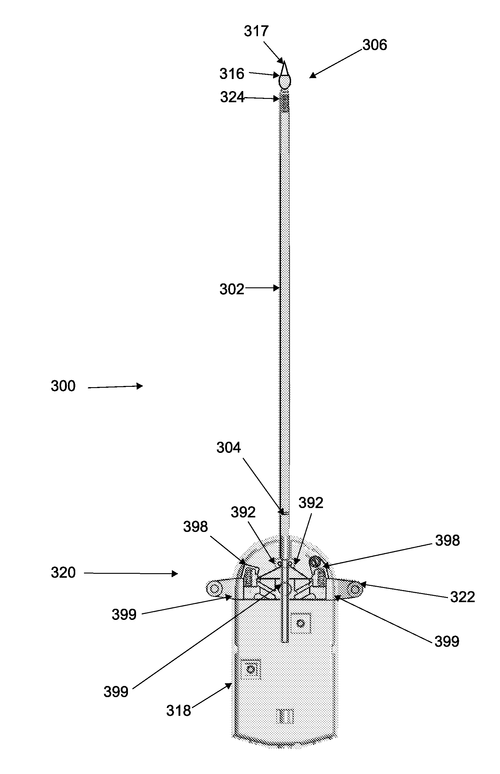
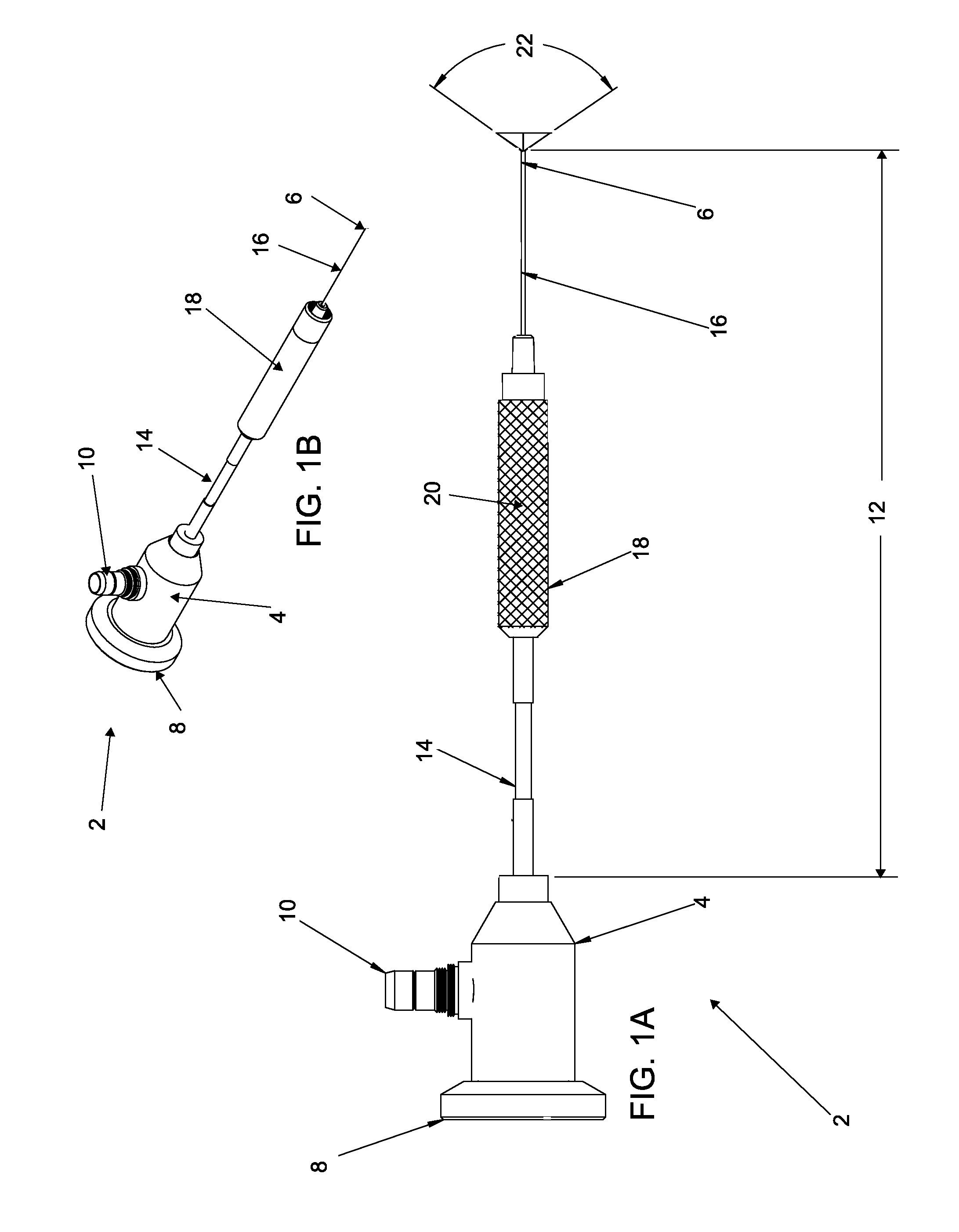
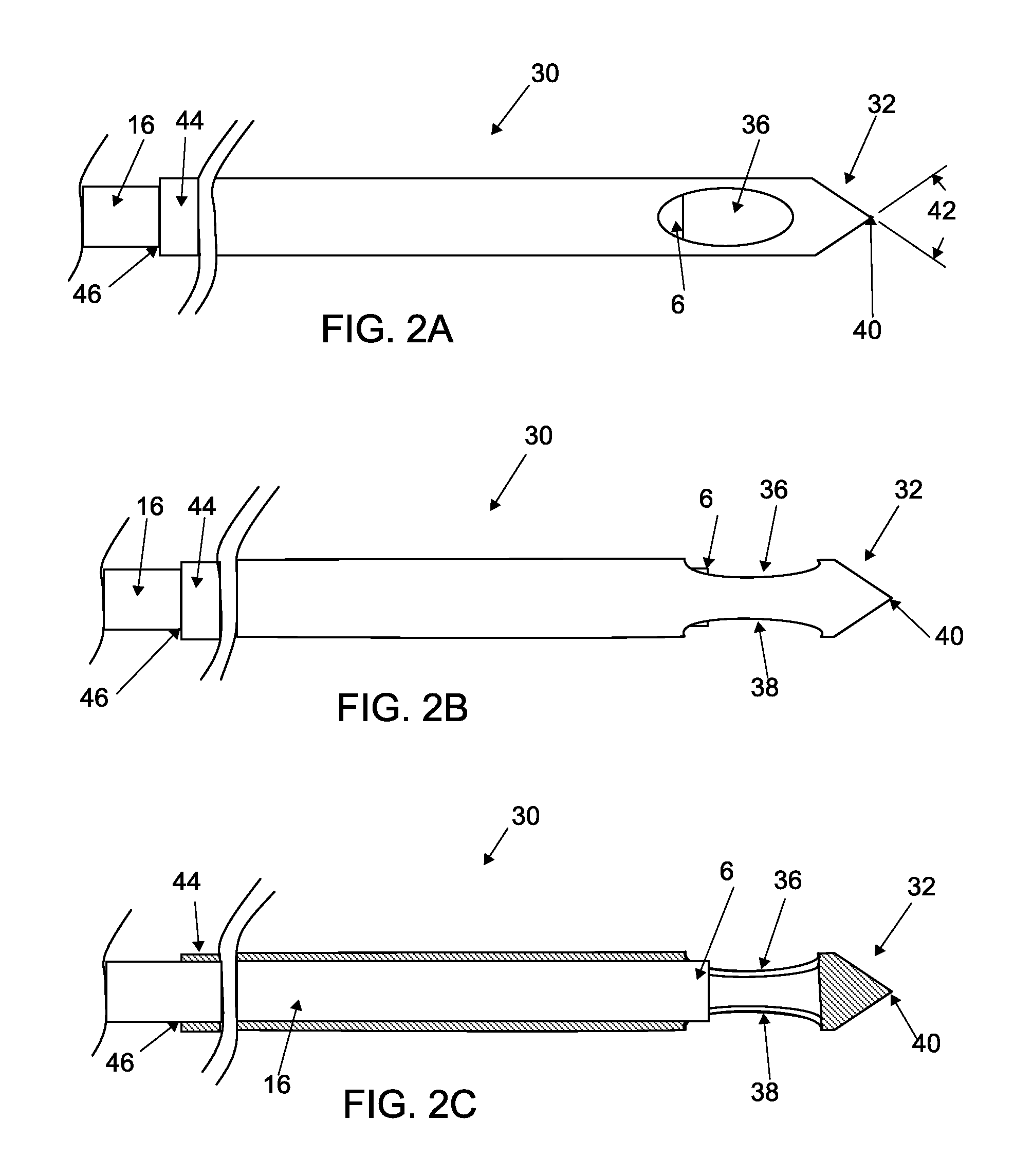
Systems and methods for accessing the spine include tissue penetrating members with direct visualization capability that may be used to form an access pathway to a targeted treatment site. The direct visualization capability, which may be provided by fiberoptic illumination and imaging components, may be use to visualize the tissue as the access pathway is formed by the tissue penetrating member. The tissue penetrating members include catheters and cannulas with sharpened tips with integrated fiberoptic components and/or channels in which a fiberscope or miniscope may be inserted. Apertures and/or transparent materials are provided to permit imaging of tissue about the distal end of the tissue penetrating member.

Description

CROSS-REFERENCE TO RELATED APPLICATIONS[0001]The present application claims priority under 35 U.S.C. §119(e) to U.S. Provisional Application No. 61 / 084,202 filed on Jul. 28, 2008, the disclosure of which is hereby incorporated by reference in their entirety.BACKGROUND OF THE INVENTION[0002]Injured intervertebral discs are generally treated with bed rest, physical therapy, modified activities, and pain medications for substantial treatment durations. There are also a number of treatments that attempt to repair injured intervertebral discs and to avoid surgical removal of injured discs. For example, disc decompression is a procedure used to remove or shrink the nucleus, thereby decompressing and decreasing the pressure on the annulus and nerves. Less invasive procedures, such as microlumbar discectomy and automated percutaneous lumbar discectomy, remove the nucleus pulposus of a vertebral disc by aspiration through a needle laterally inserted into the annulus. Another procedure involv...

Claims


Application Information

Patent Timeline
Patent Type & Authority Applications(United States)
IPC IPC(8): A61B17/34A61M29/00A61B1/04
CPCA61B17/320016A61B17/3211A61B2017/3454A61B17/3478A61B19/5212A61B17/3401A61B1/00082A61B1/00087A61B1/00096A61B1/0051A61B1/3135A61B1/3137A61B90/361
Inventor JANSEN, LEX P.CHIN, SINGFATTTO, JOHN T.
Owner EXPANDING INNOVATIONS INC
Why Eureka
Try Eureka