Hybrid working machine

a working machine and hybrid technology, applied in the direction of machines/engines, manual lubrication, couplings, etc., can solve the problems of high cost, inconvenient use, and wear of the fretting surface,

Active Publication Date: 2010-08-05
KOBELCO CONSTR MASCH CO LTD
View PDF10 Cites 11 Cited by
  • Summary
  • Abstract
  • Description
  • Claims
  • Application Information

AI Technical Summary

Benefits of technology

[0023]Also in this case there is obtained the effect of the present invention. The route including the spline coupling portion corresponds to the oil passage in the above preferred example and the oil passage is defined by the lubricating oil chamber in the generator-motor and the oil passing hole.

Problems solved by technology

In the direct coupling structure by spline coupling it is known that there occurs fretting wear (wear caused by striking of spline teeth against each other under fine vibration) by revolution fluctuation.
However, this fixing method is not suitable for practical use because not only the assembling performance is deteriorated but also a difficulty is encountered in ensuring a required space and the cost becomes high.
However, the external oiling method requires maintenance and there easily occurs deficient lubrication due to forgetting to supply oil or oil shortage.
Thus, the reliability of wear prevention is low.
Further, in the oil sealing method, not only the oil sealing work after assembly is troublesome, but also there is a fear of deficient lubrication due to deterioration or change in quality of oil.

Method used


Image

  • Hybrid working machine
  • Hybrid working machine
  • Hybrid working machine

Examples


Embodiment Construction

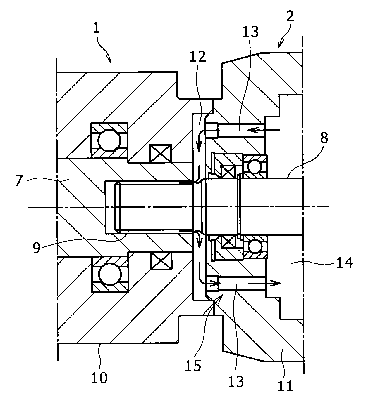
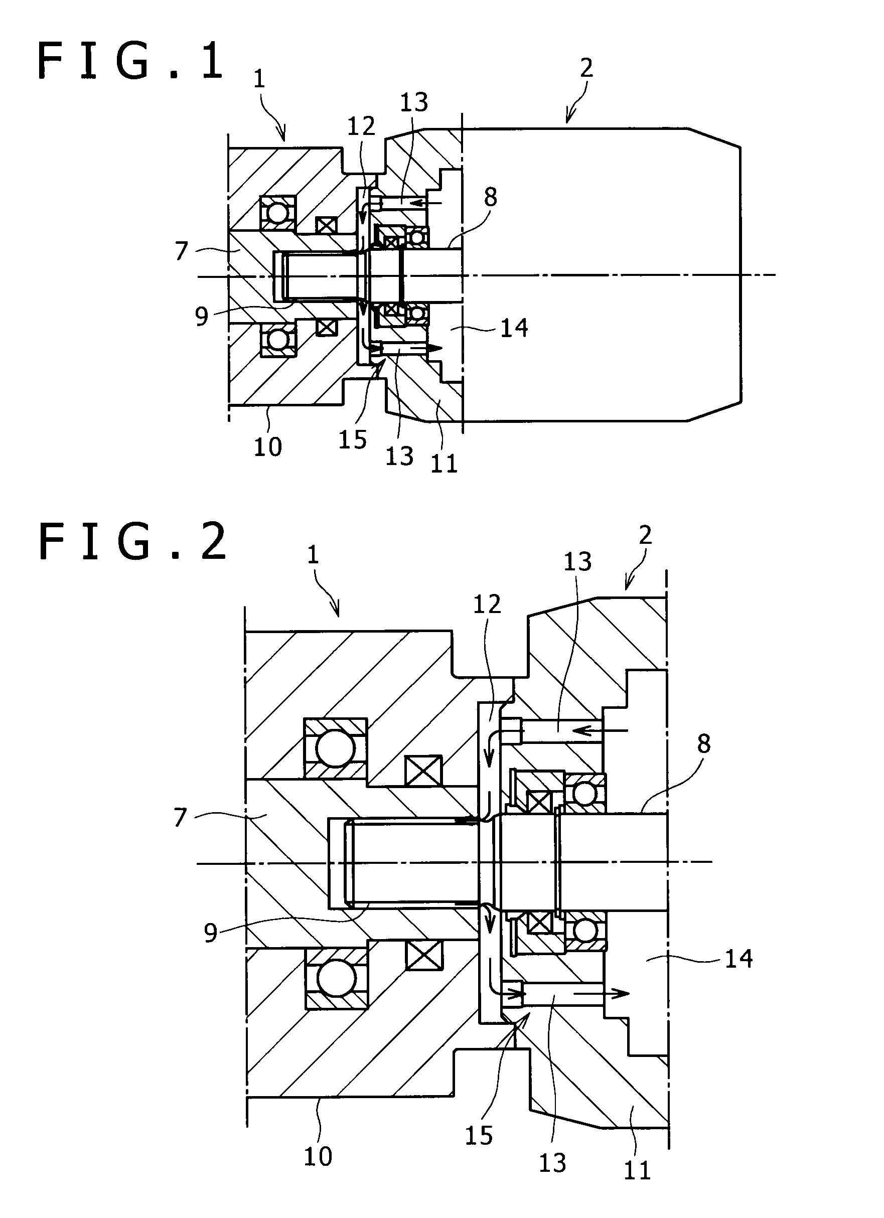
[0027]An embodiment of the present invention will be described below with reference to FIGS. 1 and 2.

[0028]A rotating shaft 7 of a generator-motor 1 and a rotating shaft (input shaft) 8 of a hydraulic pump 2 are coupled directly by spline coupling (the numeral 9 denotes a spline coupling portion) and a rotational force of an engine is transmitted from the generator-motor 1 to the hydraulic pump 2 via the spline coupling portion 9.

[0029]Numeral 10 denotes a casing (hereinafter referred to as the “motor casing”) of the generator-motor 1 and numeral 11 denotes a casing (hereinafter referred to as the “pump casing”) of the hydraulic pump 2. In the illustrated embodiment, both rotating shafts 7 and 8 are coupled together by spline coupling within the motor casing 10.

[0030]On a pump-side end portion of the motor casing 10 is formed a lubricating oil chamber 12 so as to communicate with the spline coupling portion 9.

[0031]The lubricating oil chamber 12 is formed on a pump-side end face of ...


PUM


Abstract

As lubricating construction for a spline coupling portion for connecting a rotating shaft of a generator-motor and a rotating shaft of a hydraulic pump both actuated by an engine, a lubricating oil chamber communicating with the spline coupling portion is formed within a motor casing of the generator-motor, while in a pump casing of the hydraulic pump there is formed an oil passing hole providing communication between the lubricating oil chamber and an oil chamber in the hydraulic pump on an outer periphery side of the rotating shaft of the hydraulic pump, thereby forming an oil passage for allowing working oil present within the hydraulic pump to circulate through a route including the spline coupling portion.

Description

BACKGROUND OF THE INVENTION[0001]1. Field of the Invention[0002]The present invention relates to a hybrid working machine wherein a rotating shaft of a generator-motor and that of a hydraulic pump are coupled directly by spline coupling.[0003]2. Description of the Related Art[0004]A background technique will be described below with reference to an excavator as an example.[0005]FIG. 3 shows a configuration example of a hybrid excavator.[0006]A generator-motor 1 adapted to perform both generator function and motor function and a hydraulic pump 2 serving as an oil pressure source of hydraulic actuators are connected in tandem to an engine 3 and pressure oil from the hydraulic pump 2 is supplied to plural hydraulic actuators through a control valve 4.[0007]On the other hand, a battery (an electric power storage device) 6 is charged through an inverter 5 by the generator function of the generator-motor 1 and at the same time, with the electric power stored in the battery 6, the generator...

Claims


Application Information

Patent Timeline
Patent Type & Authority Applications(United States)
IPC IPC(8): F16N9/02F16N1/00
CPCE02F9/20F16D1/101F16D2001/103H02K9/19E02F9/0866H02K7/1815H02K7/003F16D2300/06F16H57/04
Inventor SORA, TOSHIO
Owner KOBELCO CONSTR MASCH CO LTD
Why Eureka
Try Eureka