Self Sensing Integrated System and Method for Determining the Position of a Shaft in a Magnetic Bearing

Inactive Publication Date: 2010-08-05
UNIV OF VIRGINIA ALUMNI PATENTS FOUND
View PDF21 Cites 18 Cited by
  • Summary
  • Abstract
  • Description
  • Claims
  • Application Information

AI Technical Summary

Benefits of technology

[0020]It should be appreciated that the AMB has a variety of uses. Generally, it can be used in any number of applications that require the use of a bearing. In particular the AMB may have uses which include, but are not limited thereto, the following: ultracentrifuges, high speed gyros and flywheels, turbomachinery, centrifugal compressors, turboexpanders, turbines, machine tool spindles, X-ray tubes, heart pumps, fans, sea water pumps, turbine generators, and circulation pumps. AMBs have general application in many environments and given the advantages of the present invention it may be particularly useful in situations where more reliable, smaller, and lighter weight AMBs are required, such as naval vessels, aircraft, and spacecraft. The present invention may also

Problems solved by technology

Unfortunately, the state space estimate method has long been proven to have limited performance as indicated in many research articles.
As noted in Chen '014, this method is only able to estimate velocity, which limits its effectiveness for most magnetic bearing applications which require position sensing rather than velocity sensing.
Additionally, it does not work well with commonly used

Method used


Image

  • Self Sensing Integrated System and Method for Determining the Position of a Shaft in a Magnetic Bearing
  • Self Sensing Integrated System and Method for Determining the Position of a Shaft in a Magnetic Bearing
  • Self Sensing Integrated System and Method for Determining the Position of a Shaft in a Magnetic Bearing

Examples


first embodiment

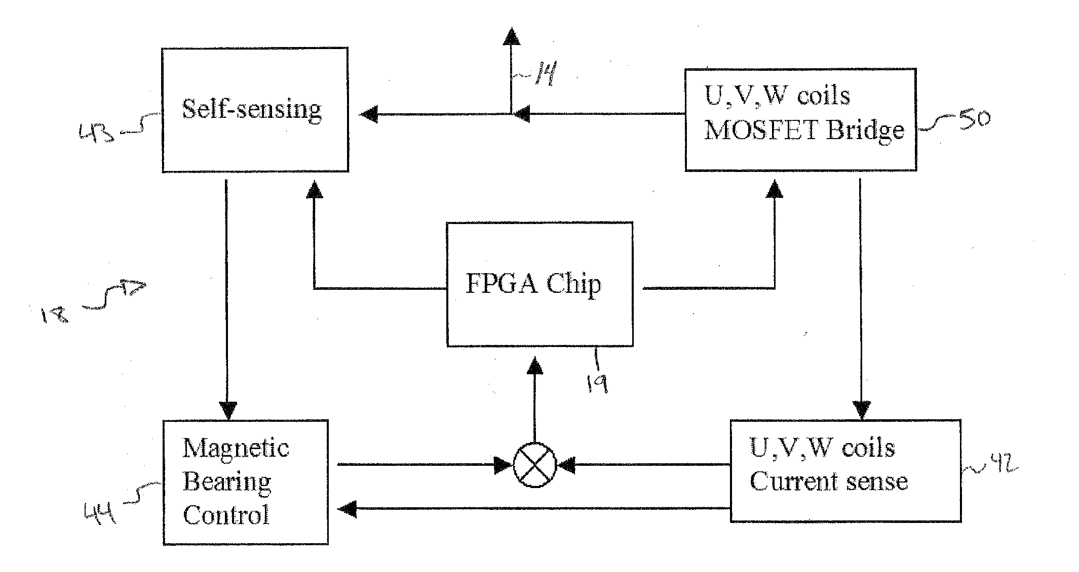
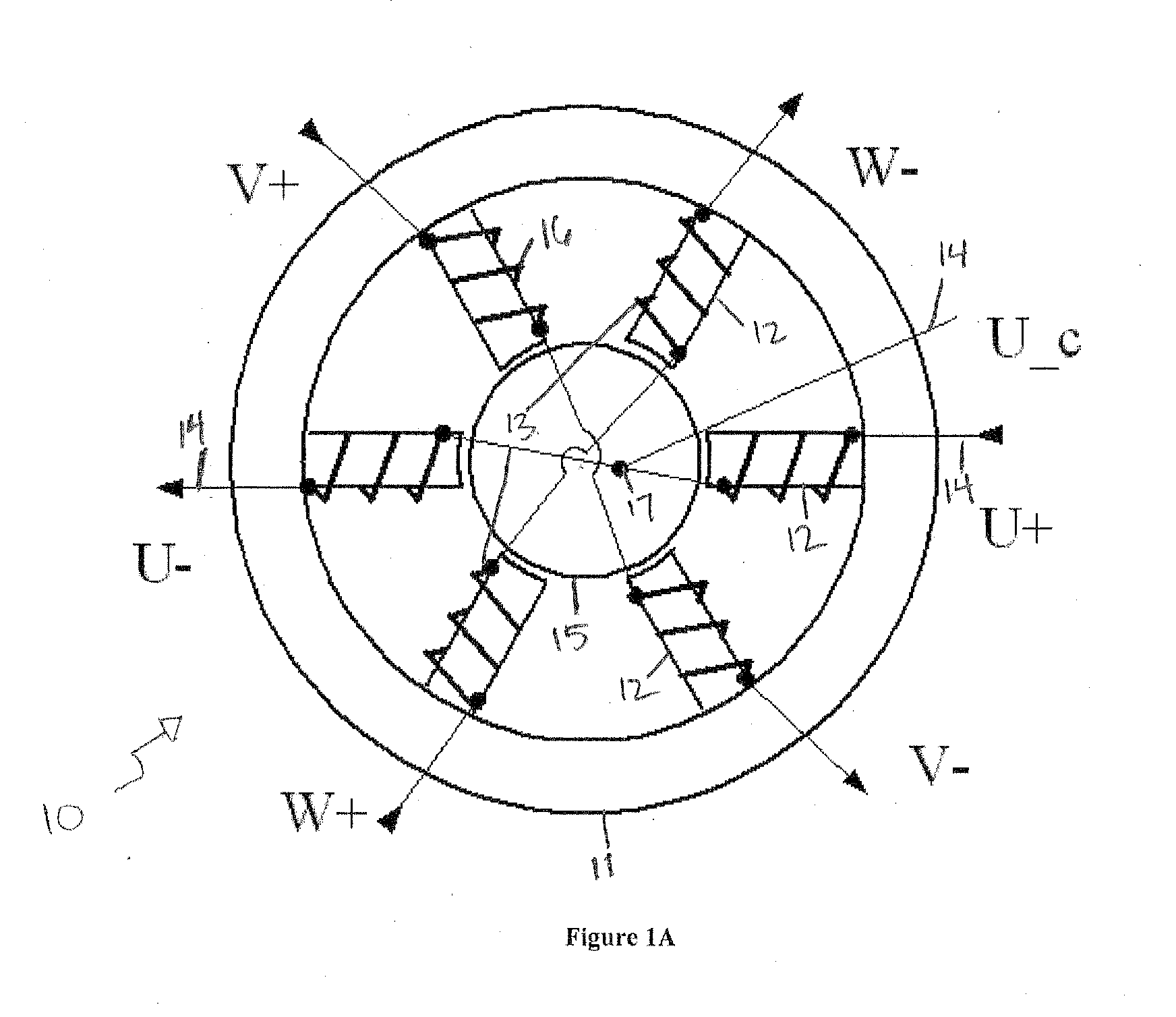
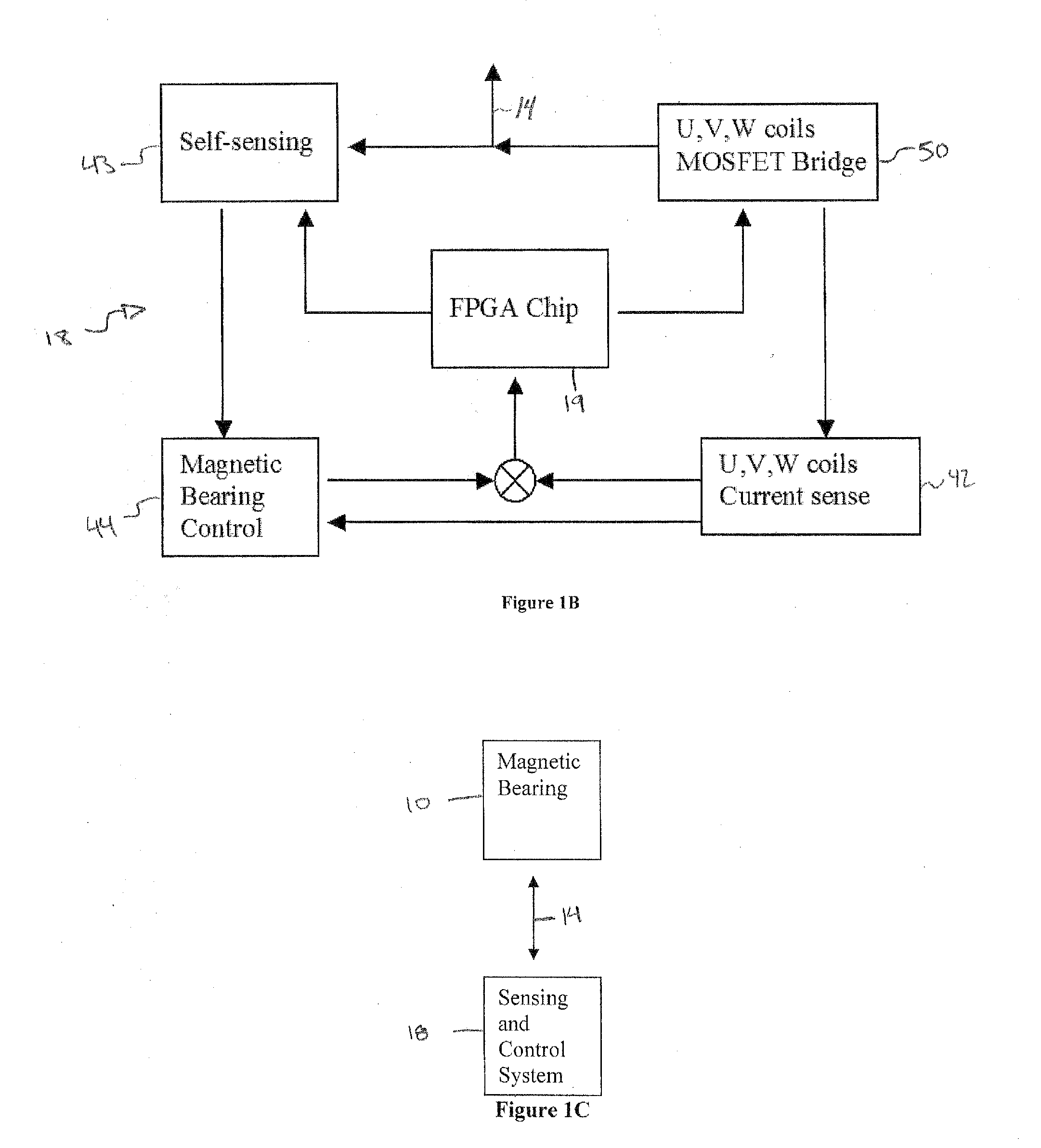
[0043]As shown in FIGS. 1(A) and 1(B), in a first embodiment constructed according to the principles of the present invention, an integrated amplifier / self-sensing circuit 18 based on FPGA chips controls the currents of the magnetic coils and the self-sensing sampling circuits, the radial magnet bearing 10 is constructed with a continuous back iron 11 and six poles 12. Other pole numbers (4, 8, etc.) can be constructed based on the same principle. A PM (or electromagnet) provides bias flux axially for the magnetic bearing. The coils on opposite poles of the magnetic bearing are connected to 3 wires 14, connecting to an end of each coil and a common node 17 as seen in FIG. 1(A). The voltage signals are applied to the coils in a time-multiplexed waveform (FIG. 6) controlled by an FPGA 19 (see FIG. 1(B)). First, a small portion of the switching cycles performs the self-sensing. This task is carried out by applying a specific voltage combination to the three pairs of coils. This combina...

second embodiment

[0059]In a second embodiment, the invention may be constructed according to the principles of the present invention for active magnetic bearings consisting of multiple poles including 4, 6, 8, 10, 12 or any even number of poles (a 4 pole example is shown in FIG. 9). Again the bearing 10 contains a continuous back iron 11 and coil pairs that are connected to the processor. These AMBs do not have a PM bias flux so the coil currents need to be controlled independently. The coils are connected in pairs corresponding to poles in opposite directions (unlike the prior art) with the center of the coil wiring circuit connected to ground via a common inductor 91. The bearing has a NSNS bias flux polarity sequence.

[0060]A typical amplifier structure is shown in FIG. 10. The amplifier controls the coil current with a three level voltage amplifier 101. The amplifier is controlled by the FPGA chip to also generate the correct voltage sequence required by self-sensing. As mentioned above, in this ...


PUM


Abstract

A magnetic bearing system and related method that utilizes self-sensing in order to determine and adjust the position of a shaft within the bearing. Magnetic bearings levitate a rotating object with a magnetic field and are unstable in open-loop operation. Position feedback control is required to maintain a rotor in a centered position. The system and related method uses a unique design to sense the position of the rotating object with greater accuracy. It comprises coils which are used both to detect and adjust the position of the rotating object and a control system which supplies signals in a time-multiplexed manner in order to determine the position with accuracy while still allowing the same coils that are used to detect position to also supply a field to control the position of the rotor.

Description

RELATED APPLICATIONS[0001]This application claims benefit of Provisional Application Ser. No. 60 / 959,635 filed Jul. 16, 2007, entitled “Self Sensing Integrated System for Determining the Position of a Shaft in a Magnetic Bearing,” of which the disclosure is hereby incorporated by reference herein in its entirety.FIELD OF THE INVENTION[0002]The present invention pertains to detecting the position of a target shaft in an active magnetic bearing (AMB) system without using a separate physical sensor.BACKGROUND OF THE INVENTION[0003]Historically, there are two primary classes of self-sensing methods; 1) state estimation and 2) inductance (displacement) measurement from switching Pulse Width Modulation (PWM) amplifier waveforms. State estimation approaches model the bearing as a linear, time-invariant system and treat the rotor position as a state to be estimated as part of linear, time-invariant feedback control. PWM-based approaches rely on the effects of the driving switching amplifier...

Claims


Application Information

Patent Timeline
IPC IPC(8): H02K7/09
CPCF04D19/042F16C32/0448F16C32/0444F04D29/058
Inventor ALLAIRE, PAUL E.JIANG, WEI
Owner UNIV OF VIRGINIA ALUMNI PATENTS FOUND
Why Eureka
Try Eureka