Vibration sensor film, vibration actuator film, vibration reduction film, and multilayer film using them

a technology of vibration sensor and actuator, which is applied in the direction of mechanical vibration separation, generator/motor, instruments, etc., can solve the problems of detector serious affecting its performance, difficult to pull out the wiring of the mesh electrode, and distortion of the piezoelectric film, etc., and achieves the effect of reducing the thickness of the vibration reduction film, high accuracy and high accuracy

Active Publication Date: 2010-08-05
FUJIFILM CORP
View PDF5 Cites 18 Cited by
  • Summary
  • Abstract
  • Description
  • Claims
  • Application Information

AI Technical Summary

Benefits of technology

[0024]According to the present invention, it is possible to detect the particular mode of vibration with high accuracy, and counteract the detected vibration with high accuracy. Since the piezoelectric polymer film itself is an object where vibration is to be detected, the thickness of the vibration sensor film, the vibration actuator film, and the vibration reduction film is reduced.

Problems solved by technology

The load body imposes on the piezoelectric film a load the weight of which depends on a vibration, and causes distortion of the piezoelectric film.
In the piezoelectric vibration sensor according to the Japanese Patent Laid-Open Publication No. 5-172839, the support plates are disposed on the mesh electrodes, and make it difficult to pull out wiring of the mesh electrodes.
Thus, an attachment position error of the detector seriously affects its performance.
Furthermore, the thickness of the detector attached to the object prevents integration of the object into a device, or causes upsizing of the device.
As a result, if the piezoelectric actuator is operated to counteract the detected vibration, there is a case where the piezoelectric actuator generates an unnecessary mode of vibration, and contrarily increases the vibration.

Method used


Image

  • Vibration sensor film, vibration actuator film, vibration reduction film, and multilayer film using them
  • Vibration sensor film, vibration actuator film, vibration reduction film, and multilayer film using them
  • Vibration sensor film, vibration actuator film, vibration reduction film, and multilayer film using them

Examples


first embodiment

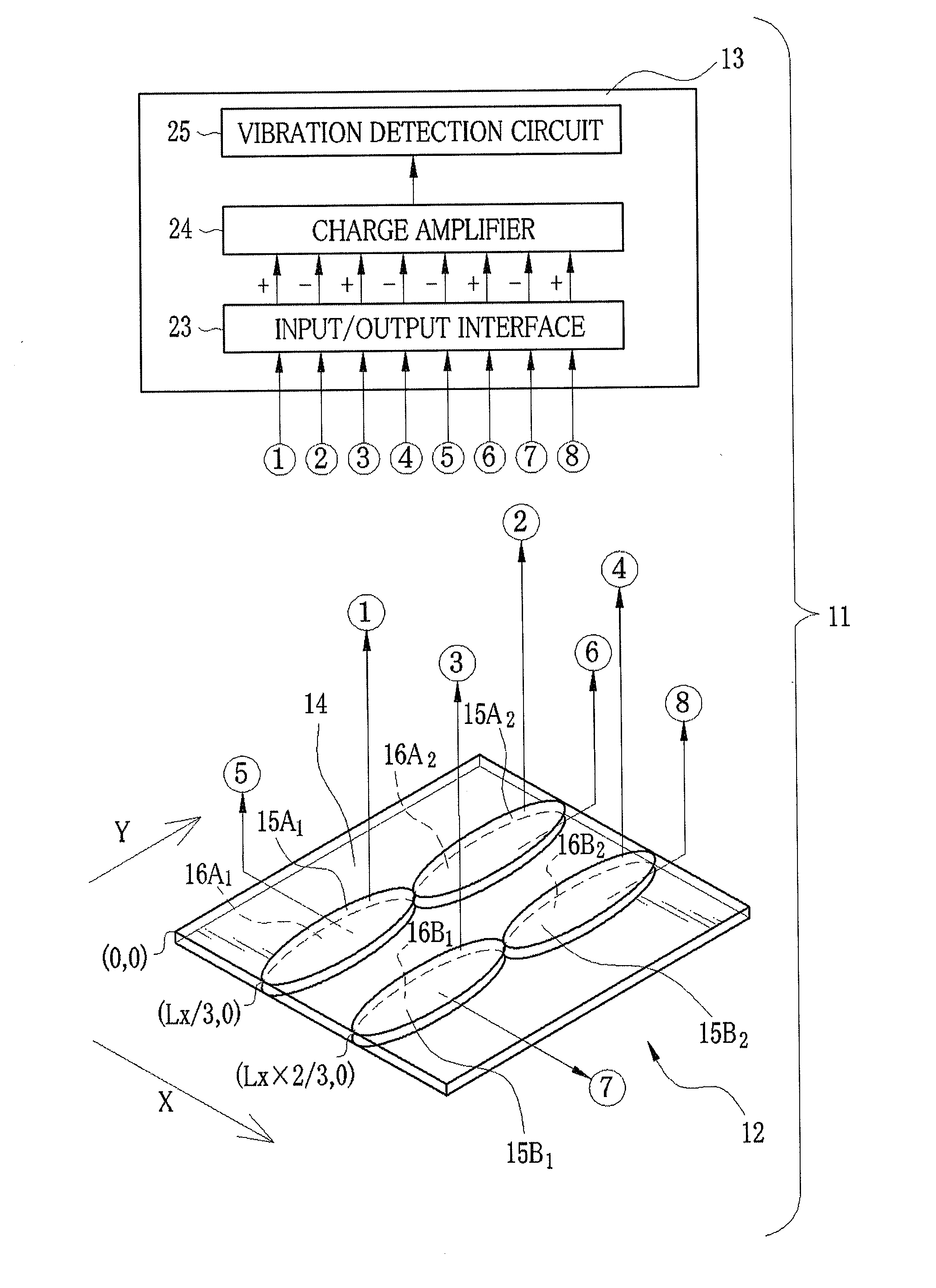
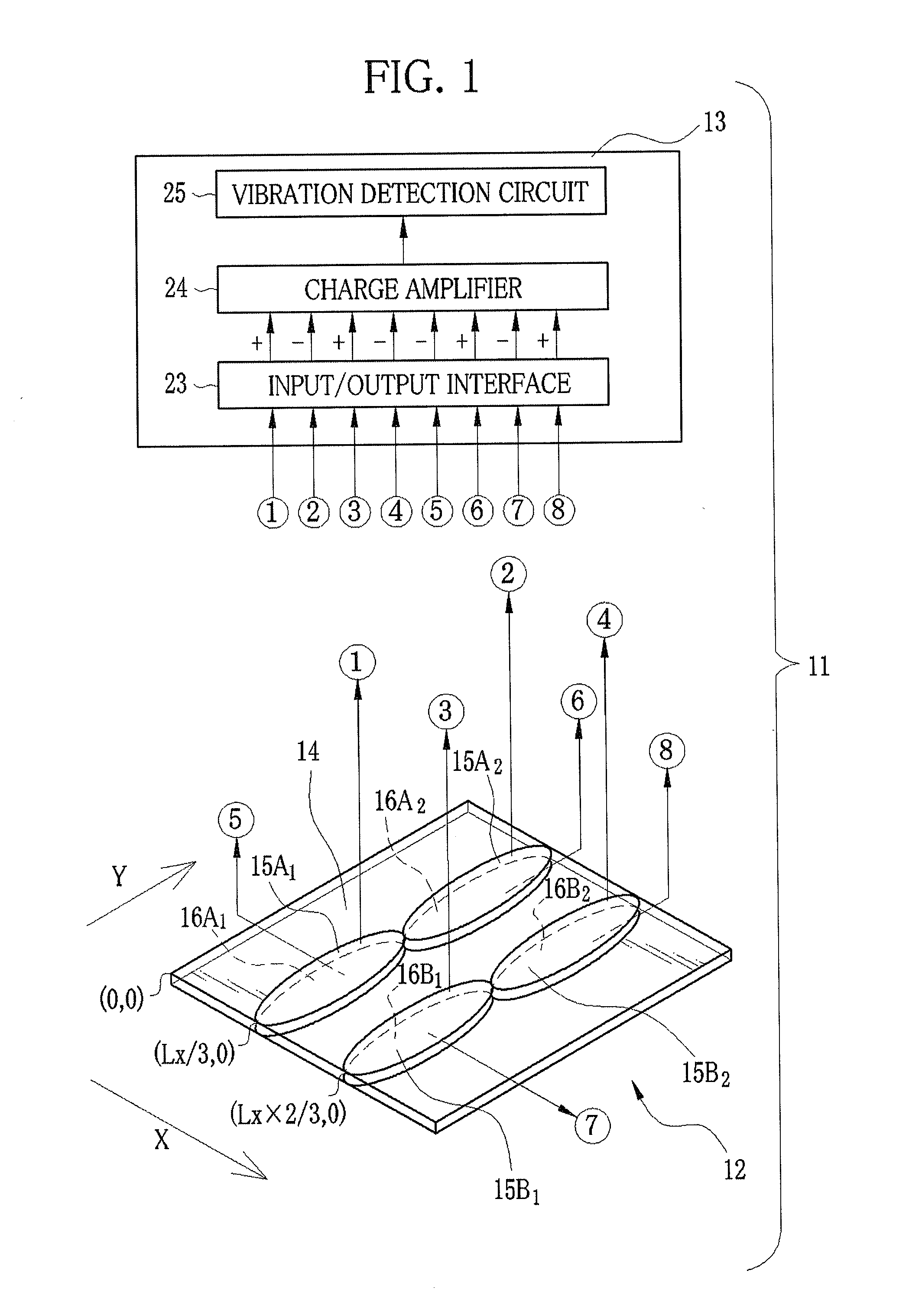
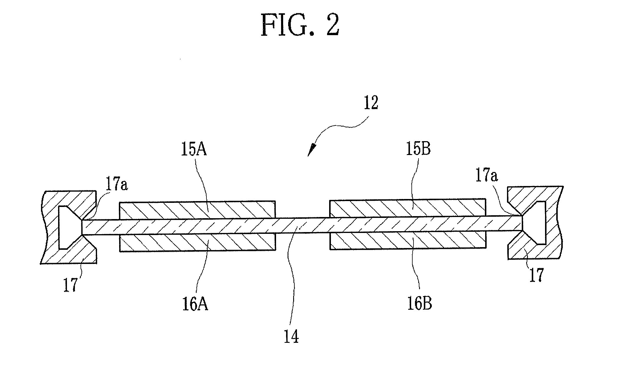
[0050]As shown in FIG. 1, a vibration sensor system 11 is constituted of a vibration sensor film 12 and a control unit 13. The vibration sensor system 11 is a system to detect vibration applied to the vibration sensor film 12. The vibration sensor film 12 is used as, for example, a building component being apart of a window or a partition. The vibration sensor film 12 is constituted of a piezoelectric polymer film 14 and electrodes (sensor electrodes) 15A, 15B, 16A, and 16B.

[0051]It is preferable that the vibration sensor film 12 be made of an organic piezoelectric material or an organic-inorganic hybrid piezoelectric material, instead of an inorganic material that is used in a conventional piezoelectric sensor and is too brittle to upsize, in consideration of a use as a plane or curved large panel, e.g. the building component for the window. From this standpoint, the piezoelectric polymer film 14 according to this embodiment is made of polyvinylidene fluoride (PVDF), but a material...

second embodiment

[0072]In the first embodiment, the piezoelectric polymer film 14 and the electrodes 15A, 15B, 16A, and 16B, or 21A, 21B, 22A, and 22B patterned on the piezoelectric polymer film 14 compose the vibration sensor film 12. However, the vibration sensor film 12 is also available as a vibration actuator film. FIG. 5 shows a vibration generator system 30 that is provided with this vibration actuator film. The vibration generator system 30 is constituted of a vibration actuator film 31 and a control unit 32. The vibration actuator film 31 has the same structure as the vibration sensor film 12 according to the first embodiment, and is constituted of a piezoelectric polymer film 14 and electrodes (drive electrodes) 33A, 33B, 34A, and 34B. The pattern of the electrodes 33A, 33B, 34A, and 34B is the same as that of the electrodes 15A, 15B, 16A, and 16B. The vibration generator system 30 of FIG. 5 generates (1st, 2nd)-order vibration by applying voltages to the electrodes 33A, 33B, 34A, and 34B....

third embodiment

[0075]A vibration reduction film that is composed of a combination of the vibration sensor film according to the first embodiment and the vibration actuator film according to the second embodiment will be described. In this vibration reduction film, the vibration sensor film detects a particular mode of vibration, and the vibration actuator film generates a canceling vibration for counteracting the detected vibration so as to reduce vibration occurring in piezoelectric polymer films. FIGS. 6 and 7 show a vibration reduction system 40 having this vibration reduction film. The vibration reduction system 40 has a vibration reduction film 41 and a control unit 42. The vibration reduction film 41 is constituted of a vibration sensor film 12 having the same structure as that of the first embodiment, a vibration actuator film 31 having the same structure as that of the second embodiment, and an insulting layer 43 sandwiched between the vibration sensor film 12 and the vibration actuator fi...


PUM


Abstract

A vibration reduction system has a vibration reduction film and a control unit. The vibration reduction film is constituted of a vibration sensor film, an insulating layer, and a vibration actuator film that are stacked in this order. In each of the vibration sensor film and the vibration actuator film, two pairs of electrodes are formed on both surfaces of a piezoelectric polymer film into a pattern based on a particular mode of vibration. The electrodes of the vibration sensor film overlap with the electrodes of the vibration actuator film. In response to electric charge signals from the electrodes of the vibration sensor film, the particular mode of vibration is detected. By application of voltages into the electrodes of the vibration actuator film, a vibration of opposite phase is generated to counteract the detected vibration.

Description

BACKGROUND OF THE INVENTION[0001]1. Field of the Invention[0002]The present invention relates to a vibration sensor film for detecting a particular mode of vibration, a vibration actuator film for generating the particular mode of vibration, a vibration reduction film for reducing the particular mode of vibration, and a multilayer film using the vibration sensor film, the vibration actuator film, or the vibration reduction film.[0003]2. Description Related to the Prior Art[0004]A piezoelectric sensor and a piezoelectric actuator that use a piezoelectric polymer film are conventionally known. In this piezoelectric sensor or the piezoelectric actuator, in general, the piezoelectric polymer film made of PVDF (polyvinylidene fluoride) is cut into a desired shape, and is glued on an object to be detected or driven.[0005]In recent years, it is proposed to use the piezoelectric sensor for vibration detection, and use the piezoelectric actuator for vibration generation. According to Japanes...

Claims


Application Information

Patent Timeline
Patent Type & Authority Applications(United States)
IPC IPC(8): B06B1/06G01H11/08H01L41/08H01L41/193H01L41/22H01L41/29H01L41/45H02N2/18H02N11/00
CPCB06B1/0696G01H11/08F16L55/0333
Inventor YONEYAMA, SATOSHI
Owner FUJIFILM CORP
Why Eureka
Try Eureka