
Micro-Electromechanical Devices Having Variable Capacitors Therein that Compensate for Temperature-Induced Frequency Drift in Acoustic Resonators

a technology of temperature-compensation capacitor and variable capacitor, which is applied in the direction of piezoelectric/electrostrictive transducers, generators/motors, transducer types, etc., can solve the problems of decreasing and achieve the effect of increasing spacing, increasing temperature, and reducing the capacitance of the temperature-compensation capacitor

Active Publication Date: 2010-08-05
INTEGRATED DEVICE TECH INC
View PDF12 Cites 21 Cited by
  • Summary
  • Abstract
  • Description
  • Claims
  • Application Information

AI Technical Summary

Benefits of technology

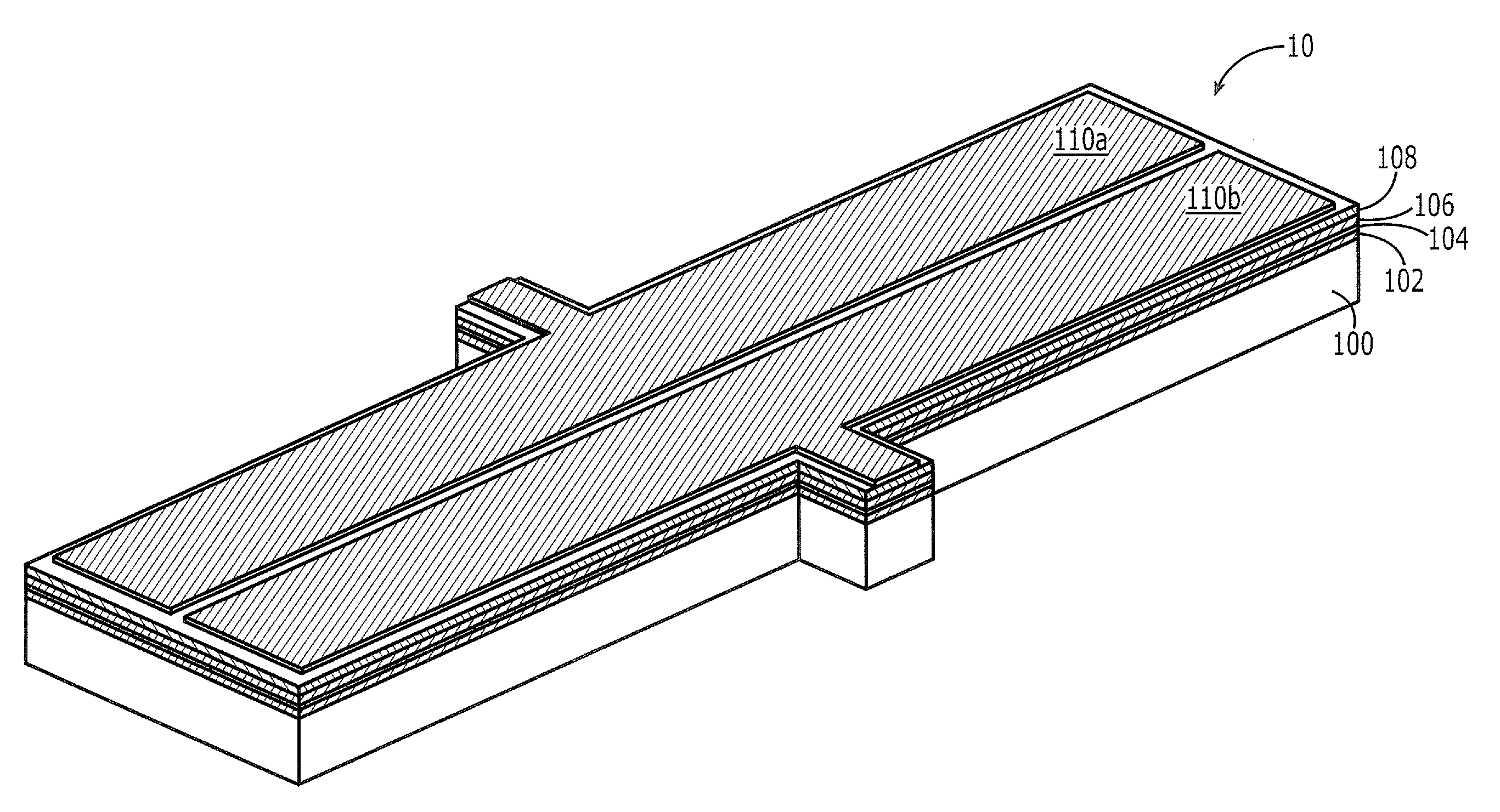
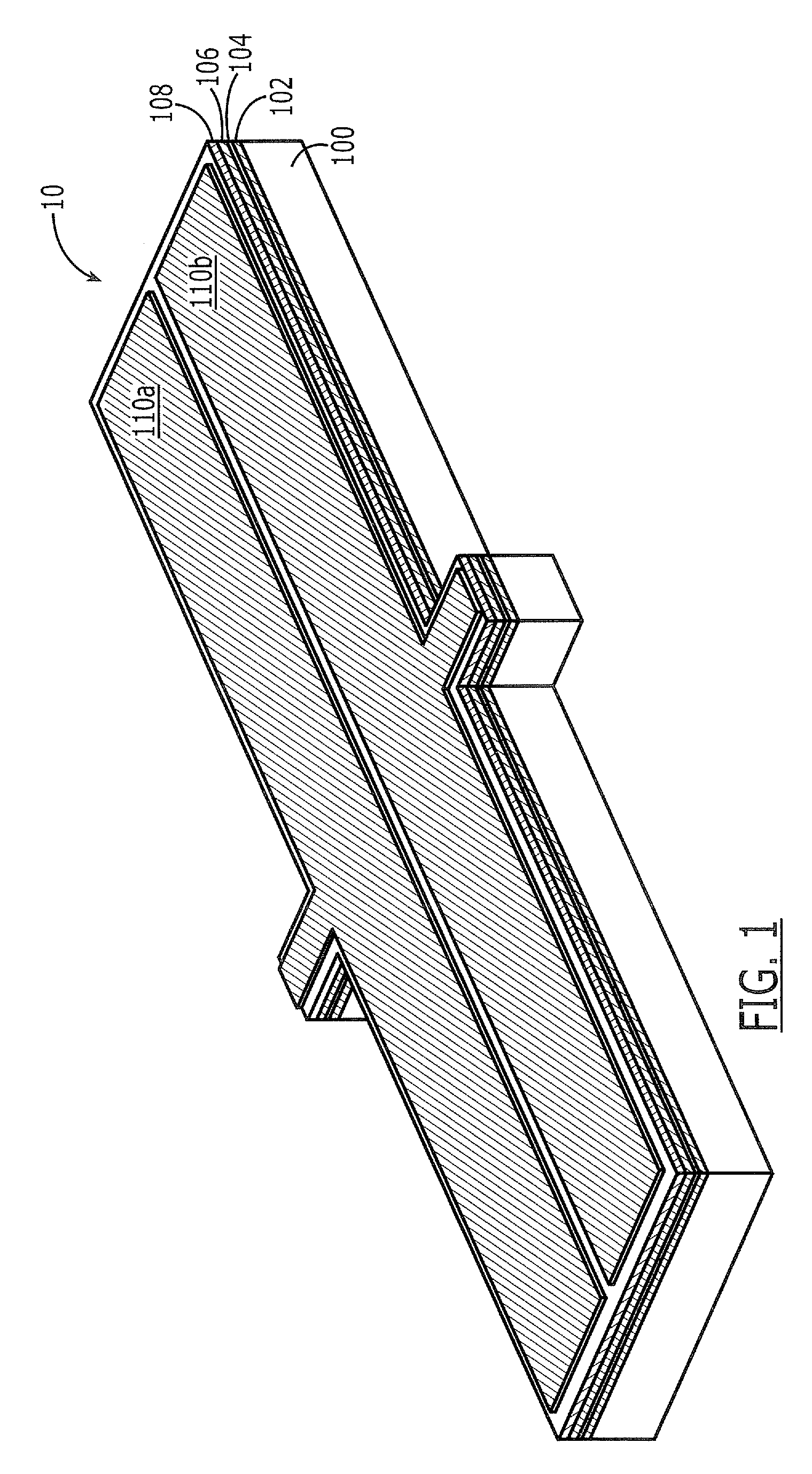
[0007]Micro-electromechanical devices according to embodiments of the present invention include a temperature-compensation capacitor and a thin-film bulk acoustic resonator having a first terminal electrically coupled to an electrode of the temperature-compensation capacitor. The temperature-compensation capacitor includes a bimorph beam having a first electrode thereon and a second electrode extending opposite the first electrode. This bimorph beam is configured to provide an increase in spacing between the first and second electrodes in response to an increase in temperature of the micro-electromechanical device. This increase in spacing between the first and second electrodes leads to a decrease in capacitance of the temperature-compensation capacitor. Advantageously, this decrease in capacitance can be used to counteract a negative temperature coefficient of frequency associated with the thin-film bulk acoustic resonator, and thereby render the resonant frequency of the micro-electromechanical device more stable in response to temperature fluctuations.

Problems solved by technology

This increase in spacing between the first and second electrodes leads to a decrease in capacitance of the temperature-compensation capacitor.

Method used


Image

  • Micro-Electromechanical Devices Having Variable Capacitors Therein that Compensate for Temperature-Induced Frequency Drift in Acoustic Resonators
  • Micro-Electromechanical Devices Having Variable Capacitors Therein that Compensate for Temperature-Induced Frequency Drift in Acoustic Resonators
  • Micro-Electromechanical Devices Having Variable Capacitors Therein that Compensate for Temperature-Induced Frequency Drift in Acoustic Resonators

Examples


Embodiment Construction

[0030]The present invention now will be described more fully with reference to the accompanying drawings, in which preferred embodiments of the invention are shown. This invention may, however, be embodied in many different forms and should not be construed as being limited to the embodiments set forth herein; rather, these embodiments are provided so that this disclosure will be thorough and complete, and will fully convey the scope of the invention to those skilled in the art. Like reference numerals refer to like elements throughout.

[0031]It will be understood that when an element or layer is referred to as being “on,”“connected to” or “coupled to” another element or layer (and variants thereof, it can be directly on, connected or coupled to the other element or layer or intervening elements or layers may be present. In contrast, when an element is referred to as being“directly on,”“directly connected to” or “directly coupled to” another element or layer (and variants thereof, th...


PUM

PropertyMeasurementUnit
thicknessaaaaaaaaaa
thicknessaaaaaaaaaa
thicknessaaaaaaaaaa

Abstract

Micro-electromechanical devices include a temperature-compensation capacitor and a thin-film bulk acoustic resonator having a first terminal electrically coupled to an electrode of the temperature-compensation capacitor. The temperature-compensation capacitor includes a bimorph beam having a first electrode thereon and a second electrode extending opposite the first electrode. This bimorph beam is configured to yield an increase in spacing between the first and second electrodes in response to an increase in temperature of the micro-electromechanical device. This increase in spacing between the first and second electrodes leads to a decrease in capacitance of the temperature-compensation capacitor. Advantageously, this decrease in capacitance can be used to counteract a negative temperature coefficient of frequency associated with the thin-film bulk acoustic resonator, and thereby render the resonant frequency of the micro-electromechanical device more stable in response to temperature fluctuations.

Description

CROSS-REFERENCE TO RELATED APPLICATION[0001]This application is a continuation-in-part of U.S. application Ser. No. 12 / 393,566, filed Feb. 26, 2009, which is a continuation-in-part of U.S. application Ser. No. 12 / 363,142, filed Jan. 30, 2009, the disclosures of which are hereby incorporated herein by reference.FIELD OF THE INVENTION[0002]The present invention relates to integrated circuit devices and, more particularly, to micro-electromechanical devices and methods of forming same.BACKGROUND OF THE INVENTION[0003]Micro-electromechanical (MEMs) resonators that are operated in a lateral bulk extension mode may have several critical parameters that can influence resonator operating frequency. Some of these critical parameters can be highlighted by modeling performance of a resonator using a simplified bulk acoustic wave equation: f=v / (2L), where f is a resonant frequency, v is an acoustic velocity of the resonator material and L is the lateral dimension of a resonator body along an ax...

Claims


Application Information

Patent Timeline
Patent Type & Authority Applications(United States)
IPC IPC(8): H03H9/00H04R17/00H10N30/00
CPCH03H9/172Y10T29/42H03H2009/241
Inventor WANG, YEBHUGRA, HARMEET
Owner INTEGRATED DEVICE TECH INC
Learn More