GPS signal transmitter and signal transmission method thereof

Inactive Publication Date: 2010-08-05
HITACHI IND EQUIP SYST CO LTD
View PDF1 Cites 4 Cited by
  • Summary
  • Abstract
  • Description
  • Claims
  • Application Information

AI Technical Summary

Benefits of technology

[0014]The present invention has been made in view of these problems as noted above and is intended to provide a technique allowing for low cost, power saving, and down sizing.
[0017]According to the present invention, it is possible to provide a technique allowing for low cost, power saving, and down sizing.

Problems solved by technology

Because of its complicated structure, the device must have a rather large size.
In addition, overall, this transmitter device cannot be operated without using components with quite a high precision.
This poses a problem that, as most of these individual components are expensive, the production cost in aggregate is high, and the device has large power consumption.
Only a single transmitter can be implemented with a single device and installation and maintenance costs are high.

Method used


Image

  • GPS signal transmitter and signal transmission method thereof
  • GPS signal transmitter and signal transmission method thereof
  • GPS signal transmitter and signal transmission method thereof

Examples


first embodiment

(1) First Embodiment

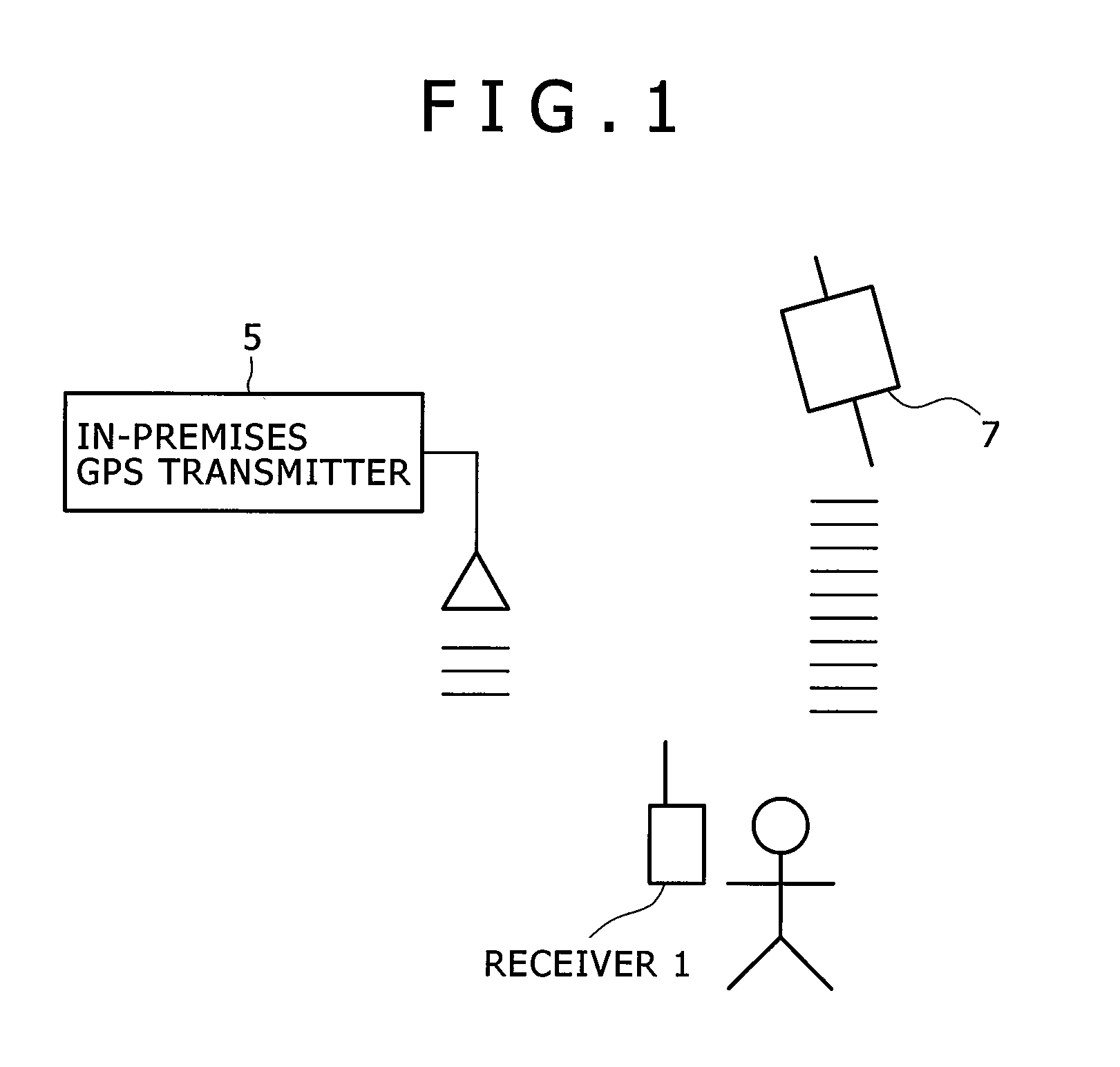
[0031]FIG. 1 is a diagram showing a location information system utilizing a GPS signal transmitter which is an embodiment of the present invention. The system includes one or more GPS signal transmitter 5 that transmits location information and a GPS signal receiver 1 (e.g., a GPS-compliant mobile terminal) that receives the information. It is assumed that the GPS signal receiver 1 is capable of receiving radio waves from an ordinary GPS satellite 7.

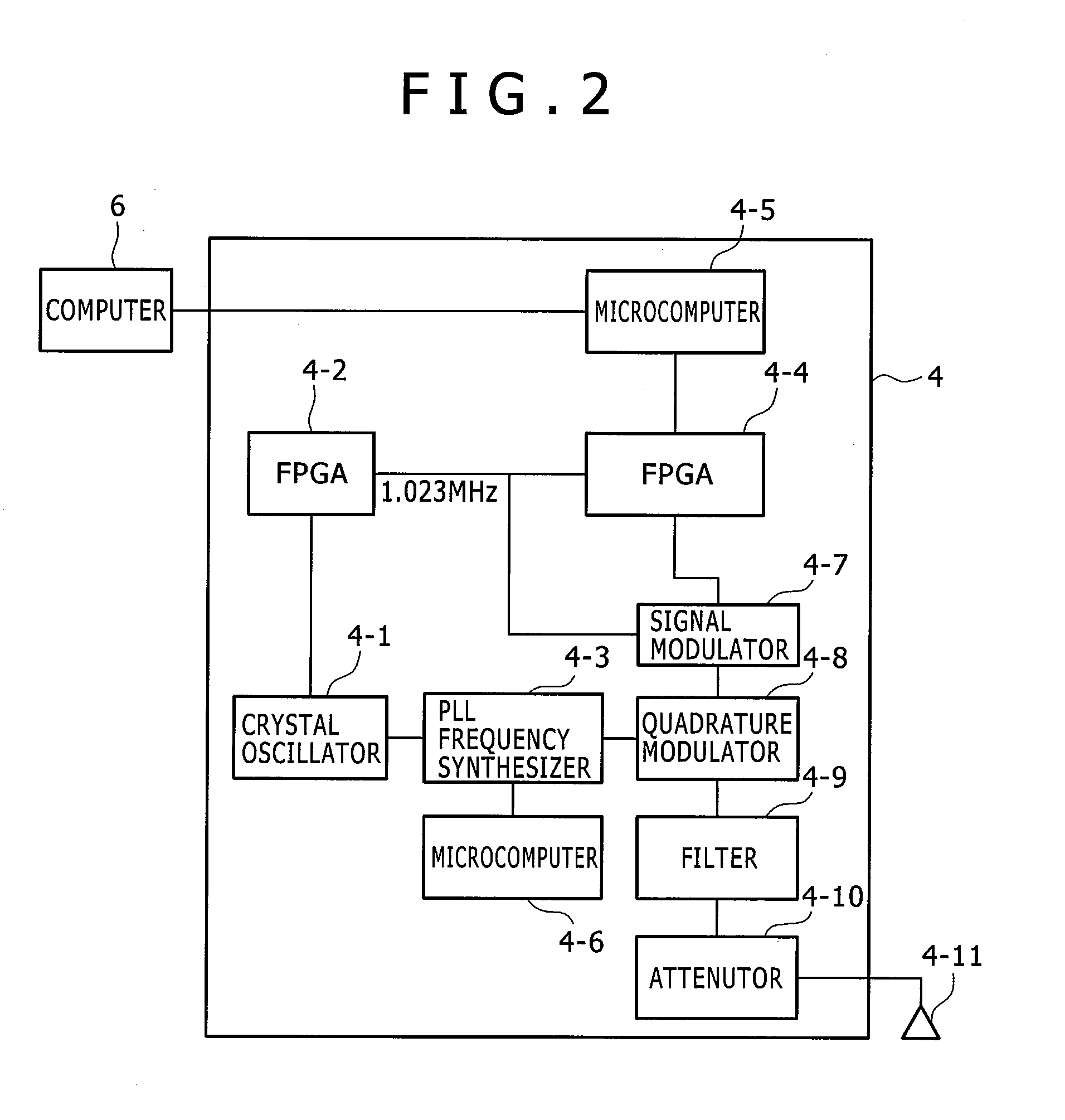
[0032]FIG. 2 is a diagram showing the hardware structure of a conventional GPS signal transmitter, which is a comparison example to which the present embodiment is compared.

[0033]A crystal oscillator 4-1 supplies a reference clock (10 MHz) to an FPGA 4-2 and a PLL frequency synthesizer 4-3.

[0034]The FPGA 4-2 generates a sync signal to drive an FPGA 4-4, using the clock received from the crystal oscillator 4-1. FPGA stands for “Field Programmable Gate Array” which refers to a programmable device in which the user can c...

second embodiment

(2) Second Embodiment

[0075]Then, a second embodiment of the present invention is described below. The configuration of the GPS signal transmitter and the functions and operations of its components in the second embodiment are the same as in the first embodiment, unless stated particularly.

[0076]FIG. 8 is a diagram showing hardware provided with a plurality of switches that receive respective bit control signals via the serial interface of the microcomputer 5-2 to generate a plurality of different in-premises GPS radio waves from a single device.

[0077]As compared with the hardware configuration shown in FIG. 3, a radio wave generating section comprised of four switches 5-4, four resistors 5-5, four filters 5-6, and four antennas 5-7 is added in FIG. 8. The PLL frequency synthesizer 5-3 provides two carrier waves having different phases in the same way as in the first embodiment, but a difference lies in that the microcomputer 5-2 provides different bit control signals to the respecti...

third embodiment

(3) Third Embodiment

[0086]Then, a third embodiment of the present invention is described below. The configuration of the GPS signal transmitter and the functions and operations of its components in the third embodiment are the same as in the first embodiment, unless stated particularly. While the examples where the GPS signal transmitter transmits its location or antenna location(s) have been presented in the first and second embodiments, an example where the GPS signal transmitter transmits signals similar to actual GPS signals transmitted by GPS satellites is discussed in the third embodiment. That is, the GPS signal transmitter transits signals simulating the signals from the GPS satellites in the third embodiment.

[0087]A description is provided for a method of implementing a simulative GPS satellite device that provides location information to a GPS signal receiver without modifying the GPS signal receiver, using the same hardware structure as shown in FIG. 8.

[0088]The reason wh...


PUM


Abstract

A GPS signal transmitter configured with a reduced number of components and achieving low cost, space saving, and low power is provided. A GPS signal transmitter of the present invention includes: a crystal oscillator; a carrier wave generator that outputs a first carrier wave and a second carrier wave whose phase is inverted to the phase of the first carrier wave, using a clock output by the crystal oscillator; a microcomputer that is driven with the clock output by the crystal oscillator and outputs a control signal based on a C / A code which is a pseudo random code; a switch that switches over between the first carrier wave and the second carrier wave according to the control signal from the microcomputer and generates a modulation wave; and an antenna that transmits the modulation wave by radio.

Description

CLAIM OF PRIORITY[0001]The present invention claims priority from Japanese patent application JP 2009-022113 filed on Feb. 3, 2009, the content of which is hereby incorporated by reference into this application.BACKGROUND OF THE INVENTION[0002]The present invention relates to a GPS signal transmitter and a signal transmission method thereof and, particularly, to a GPS signal transmitter located in a space where radio waves from satellites are not receivable and a signal transmission method thereof.[0003]A GPS (Global Positioning System) is often used to acquire location information. The GPS is one of positioning systems utilizing PGS satellites. In the GPS, a receiver receives positioning signals including time information from GPS satellites orbiting the earth at an altitude of about 20,000 kilometers and is able to know its location (in terms of latitude, longitude, and altitude) on the earth by calculation from the received positioning signals. The GPS is the system developed in ...

Claims


Application Information

Patent Timeline
IPC IPC(8): G01S19/35H04B1/04H04B1/69H04B1/707H04L27/00
CPCG01S19/11
Inventor EBATA, TOMOICHIFUJIOKA, TAKAYOSHIKAWAGUCHI, TAKAMASAYOSHIHARA, SHINYA
Owner HITACHI IND EQUIP SYST CO LTD
Why Eureka
Try Eureka