Light spot position detection device, optical device including the same, and electronic equipment including the optical device

Active Publication Date: 2010-08-05
SHARP KK
View PDF7 Cites 52 Cited by
  • Summary
  • Abstract
  • Description
  • Claims
  • Application Information

AI Technical Summary

Benefits of technology

[0063]As is apparent from the above, a given number of the frames of operation are repetitively performed in which the pixel data of only the signal light is stored in the storage portions in the memory unit, so that the pixel data of only the signal light is accumulated in the storage portions. Therefore, the position of the light spot on the pixel section can be detected with high accuracy even though the light spot position detection device of small size is used, even though the object is at a long distance, and/or even though the disturbance light is strong.
[0064]Furthermore, because the positional information on the light spot for the given number of frames is outputted whether the storage portions in the memory unit are saturated or not with the pixel data, the output timing of the positional information on the light spot can be made uniform. Thus, the control for downstream that is performed with capture of the output of the positional information on the light spot can be facilitated, and the light spot position detection device is extremely easy for users to use. In addition, positions of light spots

Problems solved by technology

Accordingly, there are many difficulties in size reduction of the device.
In terms of manufacturing cost, it is not suitable to integrate the PSD 4, having the large size, with the signal processing IC.
The conventional optical distance measuring devices, however, have such problems as follows.
Thus unstable periods of distance measuring cause a problem in that it is extremely inconvenient for downstream equipment which takes in the distance measurements to use the device.
The signal processing with use of the PSD 4 causes another problem in that it is difficult to reduce the size of the device as described above.
On c

Method used


Image

  • Light spot position detection device, optical device including the same, and electronic equipment including the optical device
  • Light spot position detection device, optical device including the same, and electronic equipment including the optical device
  • Light spot position detection device, optical device including the same, and electronic equipment including the optical device

Examples


first embodiment

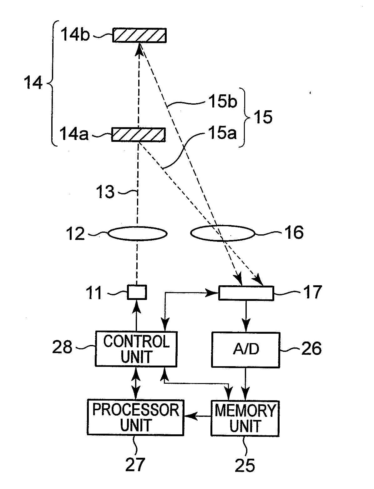
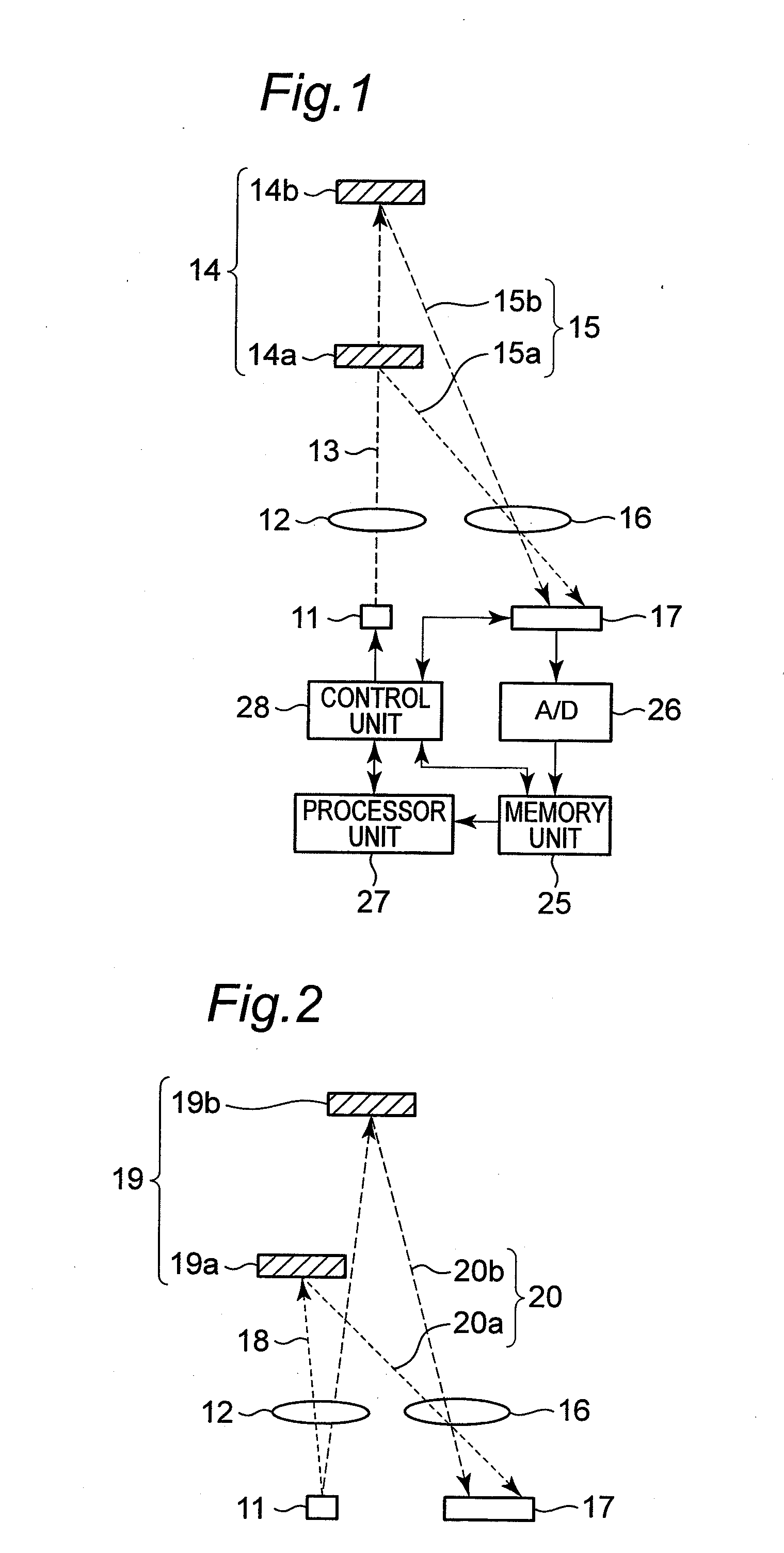
[0089]FIG. 1 is a schematic configuration of a light spot position detection device in accordance with an embodiment that is applied to an optical distance measuring device based on triangulation. In FIG. 1, light emitted from a light emitting element 11 consisting of an LED (light-emitting diode) or an LD (laser diode) is condensed by an emission lens 12 so as to be formed into a pencil of emitted light 13, and undergoes diffused reflection on a measuring object 14. A pencil 15 of reflected light is condensed by a condensing lens 16 so that a light spot image is formed on a solid-state image sensor 17. Reference sign 14a denotes the measuring object that is at a short distance and reference sign 14b denotes the measuring object that is at a long distance. Reference sign 15a denotes the pencil of light reflected by the measuring object 14a at the short distance and reference sign 15b denotes a pencil of light reflected by the measuring object 14b that is at the long distance.

[0090]A...

second embodiment

[0136]For the embodiment, the light spot position detecting device will be described with reference to an example in which the device is applied to the optical distance measuring device of reflection type shown in FIG. 1, as in the first embodiment. A configuration of the optical distance measuring device is the same as that of the optical distance measuring device shown in FIG. 1, and the description below will be given with use of FIG. 1.

[0137]FIGS. 17(a) and 17(b) are diagrams for illustrating a method for exposing the pixel section 31 in the solid-state image sensor 17 of the embodiment. FIGS. 18(a) through 18(d) show operation timing charts of the optical distance measuring device in which the light spot position detection device is installed.

[0138]In the first embodiment, all the pixels in the pixel section 31 are simultaneously exposed to light when signal light that is emitted from the light emitting element 11 and reflected by the measuring object 14 and that includes distu...


PUM


Abstract

In a light spot position detection device, in one frame of operation, under control of a control unit, pixel data obtained in a pixel section in exposure of a solid-state image sensor in synchronization with light emission of a light emitting element are added to corresponding storage portions in a memory unit, and pixel data obtained in exposure of the image sensor asynchronous to the light emission of the light emitting element are subtracted from the corresponding storage portions, to store pixel data of only signal light in the storage portions. A given number of frames of operation are repetitively performed to accumulate pixel data of only the signal light in the storage portions. The position of a light spot on the pixel section is calculated based on the pixel data of only the signal light and outputted whether the storage portions are saturated or not with the pixel data.

Description

TECHNICAL FIELD[0001]The present invention relates to a light spot position detection device for detecting a position of a light spot formed on a solid-state image sensor by an optical system, an optical device including the same, and electronic equipment including the optical device.BACKGROUND ART[0002]Optical distance measuring devices are typical among devices equipped with light spot position detection devices for detecting a position of a light spot on a solid-state image sensor which spot is formed on the solid-state image sensor by an optical system. In a measurement principle of the optical distance measuring devices, for which triangulation ranging well known to public is used, a position of a received-light spot on the solid-state image sensor is detected and a distance to a measuring object is calculated on basis of change in incident angle of a pencil of reflected light from the measuring object upon the solid-state image sensor according to the distance to the measuring...

Claims


Application Information

Patent Timeline
IPC IPC(8): H04N5/335G01S3/784G01S17/48
CPCG01S17/48G01S7/4868
Inventor WADA, HIDEO
Owner SHARP KK
Why Eureka
Try Eureka