Projector, projection system, image display method, and image display program

a projection system and projection system technology, applied in image enhancement, pulse technique, instruments, etc., can solve the problems of inability to display a normal image, large luminance difference in the edge portion, and noise such as jaggy, so as to achieve clearer image, eliminate blur, and improve image quality

Active Publication Date: 2010-08-05
SEIKO EPSON CORP
View PDF8 Cites 11 Cited by
  • Summary
  • Abstract
  • Description
  • Claims
  • Application Information

AI Technical Summary

Benefits of technology

[0022]According to this aspect of the invention, similarly to the aspect of the invention related to the projector, in the step (b), the image signal is corrected using the correction filter for correcting the difference in optical transfer function between the plurality of image projection sections, and the sharpening process is executed on the image signal thus corrected. Therefore, similarly to the aspects of the invention described above, even in the case in which the optical transfer function is different between the plurality of image projection sections, the correction into

Problems solved by technology

However, since the plurality of optical engines mounted on such a projector and the plurality of projectors constituting such a projection system each have an individual difference, and have the sharpness different from each other, there is caused a problem that it is not achievable to display a normal image by the sharpening.
Therefore, in the oblique pixel slide method, there is a problem that

Method used


Image

  • Projector, projection system, image display method, and image display program
  • Projector, projection system, image display method, and image display program
  • Projector, projection system, image display method, and image display program

Examples


first embodiment

[0034]Hereinafter, the projector according to a first embodiment of the invention will be explained with reference to the accompanying drawings.

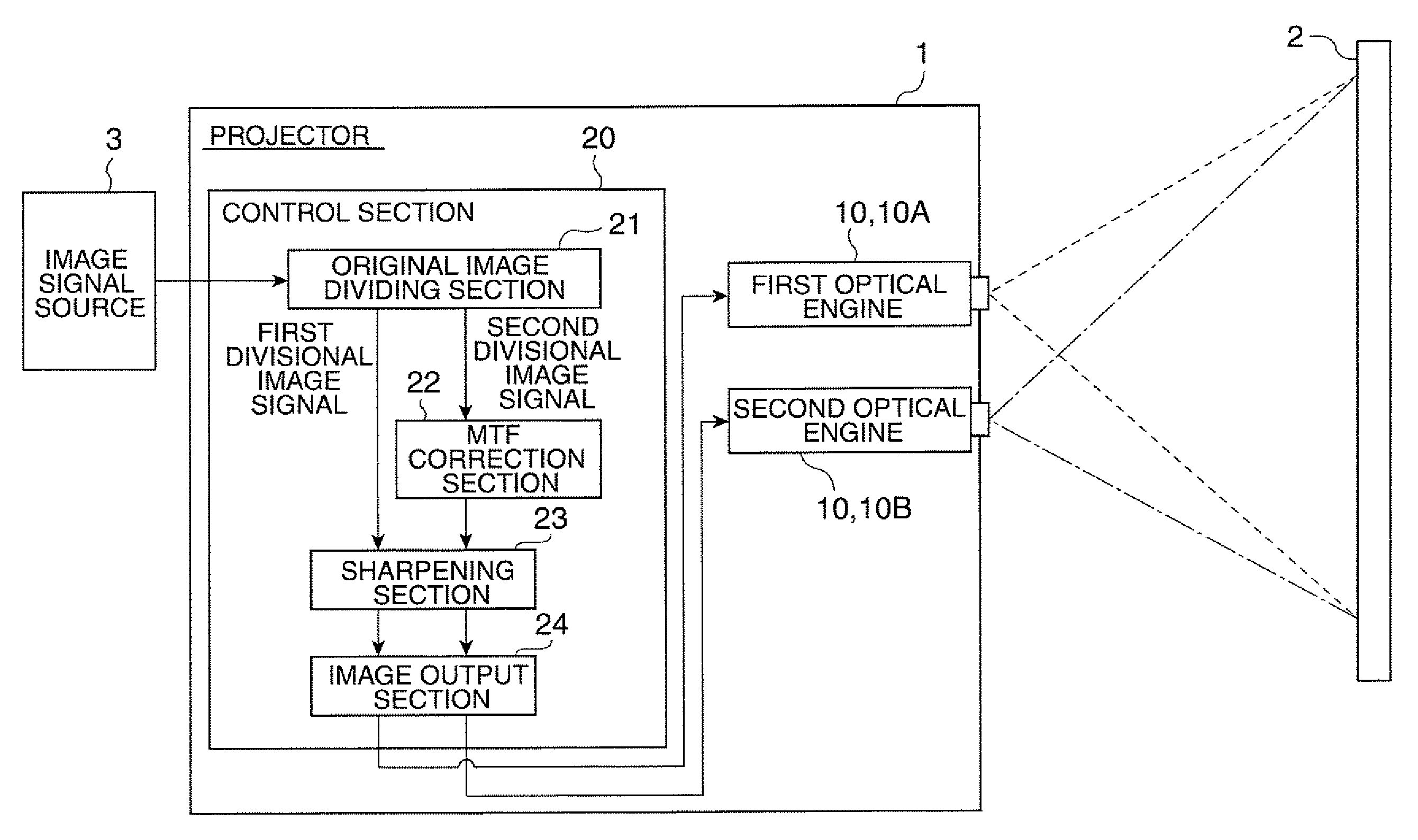
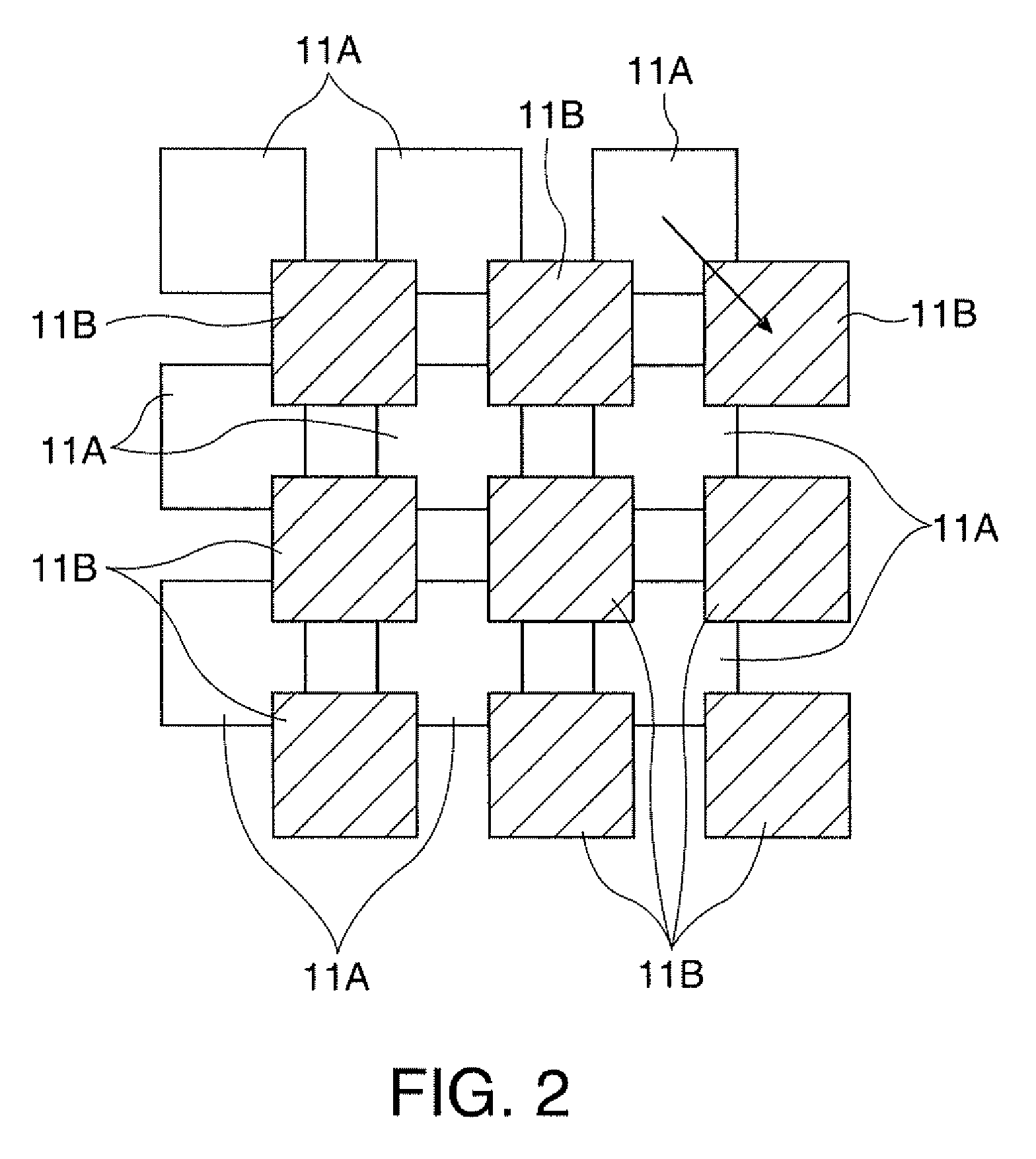
[0035]FIG. 1 is a block diagram showing a schematic configuration of the projector according to the first embodiment of the invention. FIG. 2 is a diagram showing some pixels of an image displayed on a screen.

[0036]In FIG. 1, the projector 1 is a device, which is provided with optical engines 10 (a first optical engine 10A, a second optical engine 10B) as a pair of image projection sections, and a control section 20 for inputting an image signal to each of the optical engines 10, and projects image light beams on a screen 2 from the pair of optical engines 10, thereby displaying the image on the screen 2.

[0037]Although not shown in the drawings, the pair of optical engines 10 are each provided with an illumination optical system for emitting a light beam, a separation optical system for separating the light beam emitted from the illumination...

second embodiment

[0065]Then, the projector according to a second embodiment of the invention will be explained with reference to the accompanying drawings. It should be noted that in the explanations on and after the second embodiment, the constituents identical to those of the first embodiment described above will be provided with the same reference symbols in the drawings, and the explanations therefor will be simplified or omitted.

Configuration of Projector

[0066]FIG. 6 is a block diagram showing a schematic configuration of the projector according to the second embodiment of the invention.

[0067]In FIG. 6, the projector 1A is provided with a control section 20A and the pair of optical engines 10 (10A, 10B). Similarly to the projector 1 according to the first embodiment, the projector 1A is also a projector for dividing the original image signal, which is input from the image signal source 3, into the first and second divisional image signals corresponding to the oblique pixel slide method, and out...

third embodiment

[0084]Then, a projection system according to a third embodiment of the invention will be explained with reference to the accompanying drawings.

[0085]FIG. 8 is a block diagram showing a schematic configuration of the projection system according to the third embodiment of the invention.

[0086]The projection system 30 according to the third embodiment is a system configured by substituting first and second projectors 1C, 1D for the first and second optical engines 10A, 10B of the first embodiment, respectively, and a control device 31 for the control section 20, and connecting the control device 31 to each of the projectors 1C, 1D.

[0087]The pair of projectors 1C, 1D are each provided with a single optical engine, and the engines are provided with configurations substantially identical to those of the optical engines 10A, 10B, respectively, of the first embodiment, namely the illumination optical system, the separation optical system, the light modulation optical system, the light combin...


PUM


Abstract

A projector includes: a first image projection section adapted to project a first image based on a first image signal, a second image projection section adapted to project a second image based on a second image signal such that pixels of the second image are shifted from pixels of the first image, a correction section adapted to correct the image signal input to the image projection section using a correction filter adapted to correct a difference in optical transfer function between the plurality of image projection sections; and a sharpening section adapted to execute a sharpening process of sharpening an edge portion of the image to be displayed, on the image signal having been corrected by the correction section and to be input to the plurality of image projection sections.

Description

BACKGROUND[0001]1. Technical Field[0002]The present invention relates to a projector, a projection system, an image display method, and an image display program each for sliding pixels of a plurality of image light beams from each other, thereby displaying a high-resolution image.[0003]2. Related Art[0004]In the past, there have been known image processing devices for performing a sharpening process for emphasizing a contour portion of an image in order for preventing blur and so on causing degradation in image quality (see, e.g., JP-A-9-91419 (Document 1) and JP-A-2002-83294 (Document 2)).[0005]The image processing device described in the Document 1 detects an unclear portion in the image data of the input image. Then, the image processing device executes the sharpening process using a so-called Laplacian filter of calculating quadratic differentials of the pixel value of each of the pixels of the detected portion with respect to an x-direction and a y-direction, and adding them to...

Claims


Application Information

Patent Timeline
IPC IPC(8): H04N3/26
CPCG06T2207/20192H04N5/142G06T5/20G06T5/003H04N9/3105
Inventor SAIGO, MANABU
Owner SEIKO EPSON CORP
Why Eureka
Try Eureka