
Improved stability for optical computing system

a technology of optical computing and stability, applied in the direction of instruments, measurement devices, color/spectral properties measurement, etc., can solve the problems of inability to accurately measure the data relating to one, inability to convert simple light intensity measurement to information, and inability to accurately estimate the accuracy of the estima

Active Publication Date: 2010-08-05
HALLIBURTON ENERGY SERVICES INC
View PDF6 Cites 80 Cited by
  • Summary
  • Abstract
  • Description
  • Claims
  • Application Information

AI Technical Summary

Benefits of technology

The patent describes a method for inspecting and monitoring pharmaceutical products as they move past an inspection point. The method involves using a spectral-specific light to illuminate the product, and detecting the light that carries information about the product through a special optical element. The detected light is then detected at two different locations, and the properties of the product are determined based on the detector outputs. The method also includes measuring and recording the temperature of the system to compensate for any temperature-related changes in the detector output. The method can be used for inspecting various pharmaceutical products, such as tablets, powders, or containers, and can provide high-speed, real-time monitoring.

Problems solved by technology

In general, a simple measurement of light intensity is difficult to convert to information because it likely contains interfering data.
It is often impossible to adequately measure the data relating to one of these factors since the contribution of the other factors is unknown.
Depending on the circumstances, however, the estimate may be unacceptably inaccurate since factors other than ethylene may affect the intensity of the wavelength bands.
Unfortunately, however, charge couple devices and their required operational instrumentation are very expensive.
Furthermore, the devices are sensitive to environmental conditions.
The power requirements, cooling requirements, cost, complexity and maintenance requirements of these systems have made them impractical in many applications.

Method used


Image

  • Improved stability for optical computing system
  • Improved stability for optical computing system

Examples


Embodiment Construction

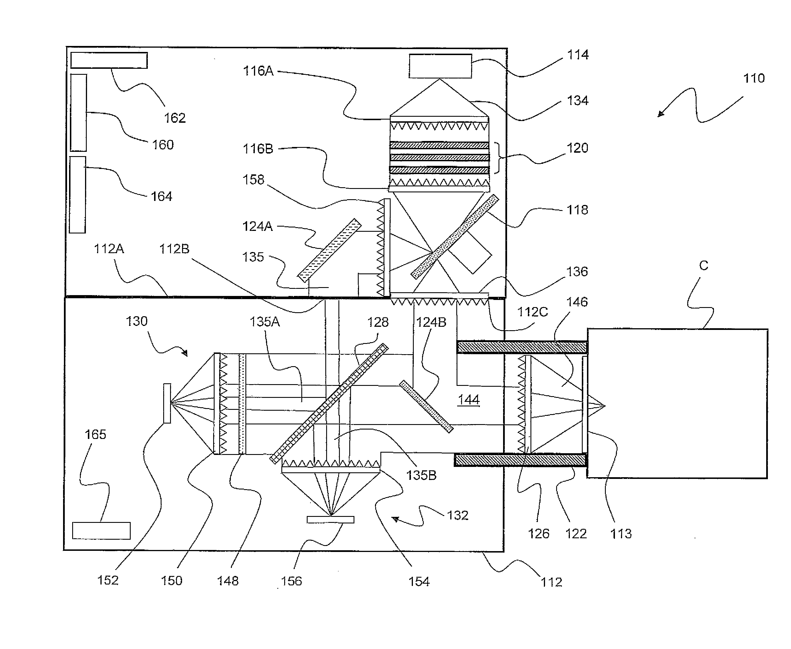
[0035]Detailed reference will now be made to the drawing in which an example embodying the present invention is shown. As used herein, the term “light” is broadly used to mean any form of radiation or radiative energy including, for instance, visible light or light in the infrared region. “Light” is also referred to herein as a light signal, a light beam, a light ray and the like to mean any form of radiative energy in the electromagnetic spectrum. Similarly, the term “transmission” can mean transmission of radiative energy onto a surface of a sample; penetration, however slight, into a sample such as a particulate sample or opaque fluid sample; or passage through a sample.

[0036]As used herein, the sample being evaluated can be a solid or a fluid including but not limited to a powder, a pharmaceutical powder mixed with lactose and other excipient materials, a chemical, a polymer, a petroleum product, a solution, a dispersion, an emulsion and combinations of these solids and fluids.

[...


PUM

PropertyMeasurementUnit
temperatureaaaaaaaaaa
transparentaaaaaaaaaa
physicalaaaaaaaaaa

Abstract

The present subject matter relates to methods of high-speed analysis of product samples. Light is directed to a portion of a product under analysis and reflected from or transmitted through the product toward an optical detector. Signals for the detector are compared with reference signals based on a portion of the illuminating light passing through a reference element to determine characteristics of the product under analysis. Temperature within the analysis system is monitored and the output signals of the optical detectors are compensated or corrections are made within the analysis calculations to compensate or correct for the system temperature. The products under analysis may be stationary, moved by an inspection point by conveyor or other means, or may be contained within a container, the container including a window portion through which the product illuminating light may pass.

Description

CROSS-REFERENCE TO RELATED APPLICATION[0001]The present application is related to U.S. Provisional Patent Application Ser. No. 60 / 856,192 filed Nov. 2, 2006, the content of which is incorporated herein by reference. The present application claims priority to U.S. Provisional Patent Application Ser. No. 60 / 920,996 file Mar. 30, 2007.FIELD OF THE INVENTION[0002]The present invention relates to improvements related to system design, fabrication and operation of multivariate optical elements. More particularly, the invention relates to methodologies of using multivariate optical computing systems to illuminate a sample in which information about the sample can be analyzed from the reflected or transmitted light in real time or near real time.BACKGROUND OF THE INVENTION[0003]Light conveys information through data. When light interacts with matter, for example, it carries away information about the physical and chemical properties of the matter. A property of the light, for example, its i...

Claims


Application Information

Patent Timeline
Patent Type & Authority Applications(United States)
IPC IPC(8): G01N21/59G01N21/55
CPCG01N35/021G01N21/31
Inventor MYRICK, MICHAEL L.FREESE, ROBERT P.SOLTMANN, WILLIAMPERKINS, DAVID L.ZHELEZNYAK, LEONARD
Owner HALLIBURTON ENERGY SERVICES INC
Learn More