Unique security device for the identification or authentication of valuable goods, fabrication process and method for securing valuable goods using such a unique security device

a security device and unique technology, applied in the field of unique security devices, can solve the problems of limiting the maximum size achievable by the available area, and the approach would not be appropriate, and achieve the effect of reducing the amount of space availabl

Active Publication Date: 2010-08-05
CSEM CENT SUISSE DELECTRONIQUE & DE MICROTECHNIQUE SA RECH & DEV
View PDF5 Cites 48 Cited by
  • Summary
  • Abstract
  • Description
  • Claims
  • Application Information

AI Technical Summary

Benefits of technology

[0010]An object of the present invention is to alleviate the drawbacks of the prior art by proposing a security device whi

Problems solved by technology

Since devices becomes smaller and smaller, the limiting factor concerning the maximal size achievable is the area available to make the mark.
This approach would

Method used


Image

  • Unique security device for the identification or authentication of valuable goods, fabrication process and method for securing valuable goods using such a unique security device
  • Unique security device for the identification or authentication of valuable goods, fabrication process and method for securing valuable goods using such a unique security device
  • Unique security device for the identification or authentication of valuable goods, fabrication process and method for securing valuable goods using such a unique security device

Examples


example 1

[0275]From the fingerprint image, a laplacian pyramid is built, a list of local maxima is found, and are located in the corresponding lowpass image of the pyramid as described in A. Oppenheim and R. Schafer, “Discrete-Time Signal Processing”, 2nd Ed, Prentice Hall, Engelwood Cliffs, N.J. 07632, 1989. For each maxima, a local orientation is computed using the local image gradient, and a 17×17 neighborhood is extracted around the maxima locations. The 17×17 neighborhood can be represented by a vector B of dimension 289.

[0276]In an early stage of the project, i.e. before deploying the invention, one has to take a large number of fingerprint images (for example 1000), and extract the vectors B using the above mentioned technique. This results in approximately 1 million vectors B, on which a Singular Value Decomposition (SVD) can be computed (cf. H. Press, S. Teukolsky, W. Vetterling and B. Flannery, “Numerical Recipes in C++”, 2nd Ed., Cambridge University Press, 2003). From there, a di...

example 2

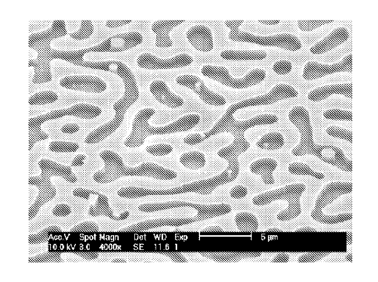
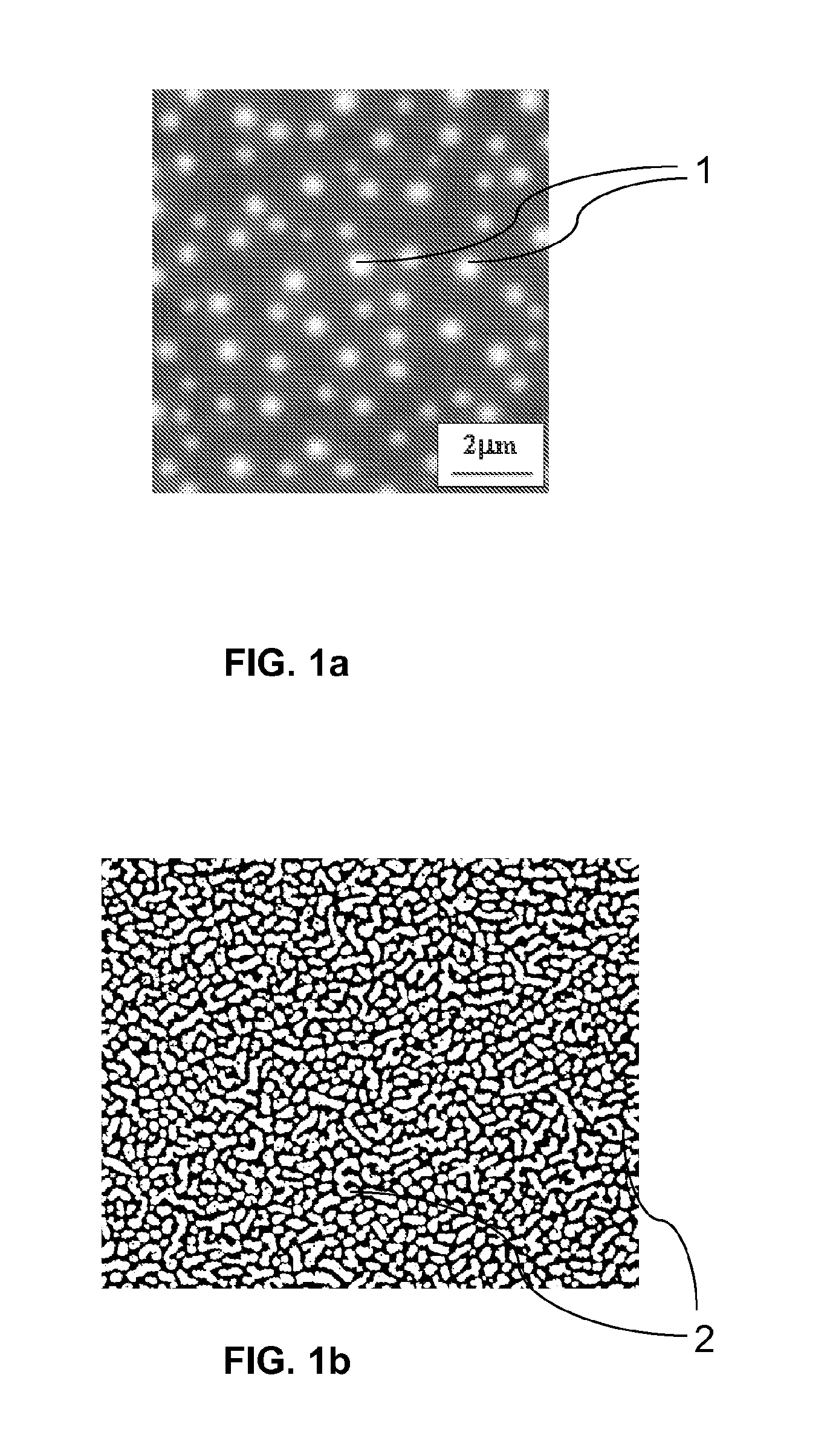
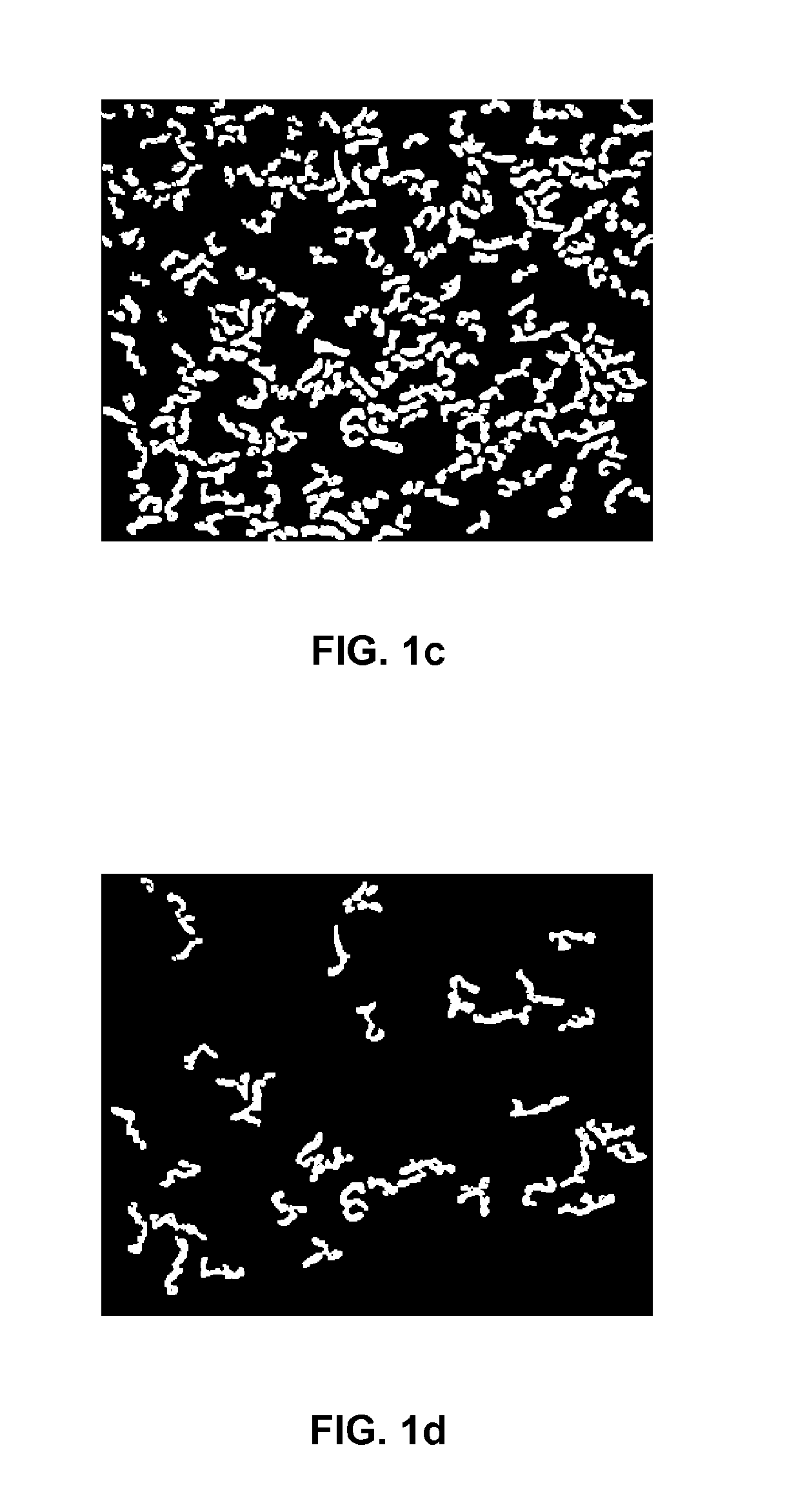
[0279]The fingerprint image is transformed into a binary image. Pixels that have values above a local mean are given value 1, the others are given value 0. To avoid merging two contiguous blobs, a morphological operation of erosion followed by dilation can be performed. Then, a connected component procedure is run. The result is an image whose pixel values are integer indices: the pixels inside a polymer blob have all the same index, and the pixel of two distinct blobs have different values. From this representation, it is trivial to treat each blob separately in a new window.

[0280]The centre of gravity of the blob is used to define the position P of the blob in the image. The blob is copied in a n×n sub-image, where n is large enough to contain the largest blob, and where the centre of gravity of the blob is set in the centre of the image. By performing a Principal Component Analysis of the sub-image (cf. H. Press, S. Teukolsky, W. Vetterling and B. Flannery, “Numerical Recipes in ...


PUM


Abstract

A security device for the identification or authentication of valuable goods is described, including a thin material layer (22, 26) presenting a stochastic pattern including micro/submicrostructures, where the latter are arranged in blobs (2) each of which presents a complexity factor
Cx=L24π·A,
where L is the perimeter of the blob and A its area, and wherein blobs having a Cx value greater than or equal to 2 cover at least 5%, preferably at least 15%, of the device surface. According to a preferred embodiment, the material layer may include a film including at least a first and a second polymers arranged respectively within a first and a second phases defining the micro/submicrostructures. Preferred processes of fabrication are also disclosed, as well as a method for securing a valuable good based on such a security device.

Description

TECHNICAL FIELD[0001]The present invention relates to a unique security device that may be applied on a valuable good to prevent counterfeiting of the latter or to allow its identification or authentication to follow the goods all along their fabrication and life times. Examples of valuable goods on which such a mark may be applied are works of art like paintings, consumer goods such as watches, or semiconductor devices, micro-electromechanical systems (MEMS), and more generally products fabricated using micro-technology processes. Furthermore, the invention also concerns a process for the fabrication of such a security device, as well as a method of identification or authentication of a valuable good based on the use of such a security device.[0002]More particularly, it is intended to provide the security device with a thin material layer presenting a stochastic pattern comprising microstructures which, upon reading with a specific reader, may generate an image data which could be ...

Claims


Application Information

Patent Timeline
IPC IPC(8): G06K9/62G06K19/00B05D5/00B05D3/12B05D5/06B05D3/10H01L21/20
CPCG06K19/086B42D25/00B42D25/29B42D25/23B42D25/445
Inventor BLONDIAUX, NICOLASHASLER, DAVIDPUGIN, RAPHAELFRANZI, EDOARDO
Owner CSEM CENT SUISSE DELECTRONIQUE & DE MICROTECHNIQUE SA RECH & DEV
Why Eureka
Try Eureka