
Vented dispensing device and method

a technology of vented dispensing and vented cylinders, which is applied in the field of vented dispensing devices and methods, can solve the problems of large size and weight, large driving mechanisms, and relatively large devices, and achieve the effect of increasing the transmission of sound waves

Active Publication Date: 2010-08-05
ROCHE DIABETES CARE INC
View PDF64 Cites 24 Cited by
  • Summary
  • Abstract
  • Description
  • Claims
  • Application Information

AI Technical Summary

Benefits of technology

[0019]In some embodiments, a selective membrane covers the vent to prevent water from entering into the dispensing patch unit.
[0064]Maintaining the pressure equilibrium in the interior of the at least one housing may include maintaining the pressure equilibrium in the interior of the at least one housing to facilitate controlled delivery of therapeutic fluid from at least one reservoir disposed inside the at least one housing, the reservoir adapted to hold therapeutic fluid to be dispensed by the fluid dispensing device.

Problems solved by technology

A drawback of these devices is their relatively large sizes and weights, resulting by their physical configuration and the relatively large driving mechanisms, e.g., syringes and pistons.
These relatively bulky devices have to be carried in patients' pockets or be attached to the patients' belts.
Such uncomfortable bulky fluid delivery devices each having a relatively long tube are disfavored by the majority of diabetic insulin users because these devices interfere with the patients' regular activities, such as sleeping, exercising, etc.
A drawback of these 2nd generation devices is their relative bulkiness and their high cost of manufacture.
Particularly, the reservoirs used in conjunctions with these devices are typically tubular and syringe-like, thus requiring a relatively large occupying space and relatively large physical dimensions (e.g., large thickness).
Another drawback of second generation devices is that users have to discard the entire device, including expensive electronics and the driving mechanisms of the devices, every 2-3 days.
Such a patch unit may be water tight as well.

Method used


Image

  • Vented dispensing device and method
  • Vented dispensing device and method
  • Vented dispensing device and method

Examples


Embodiment Construction

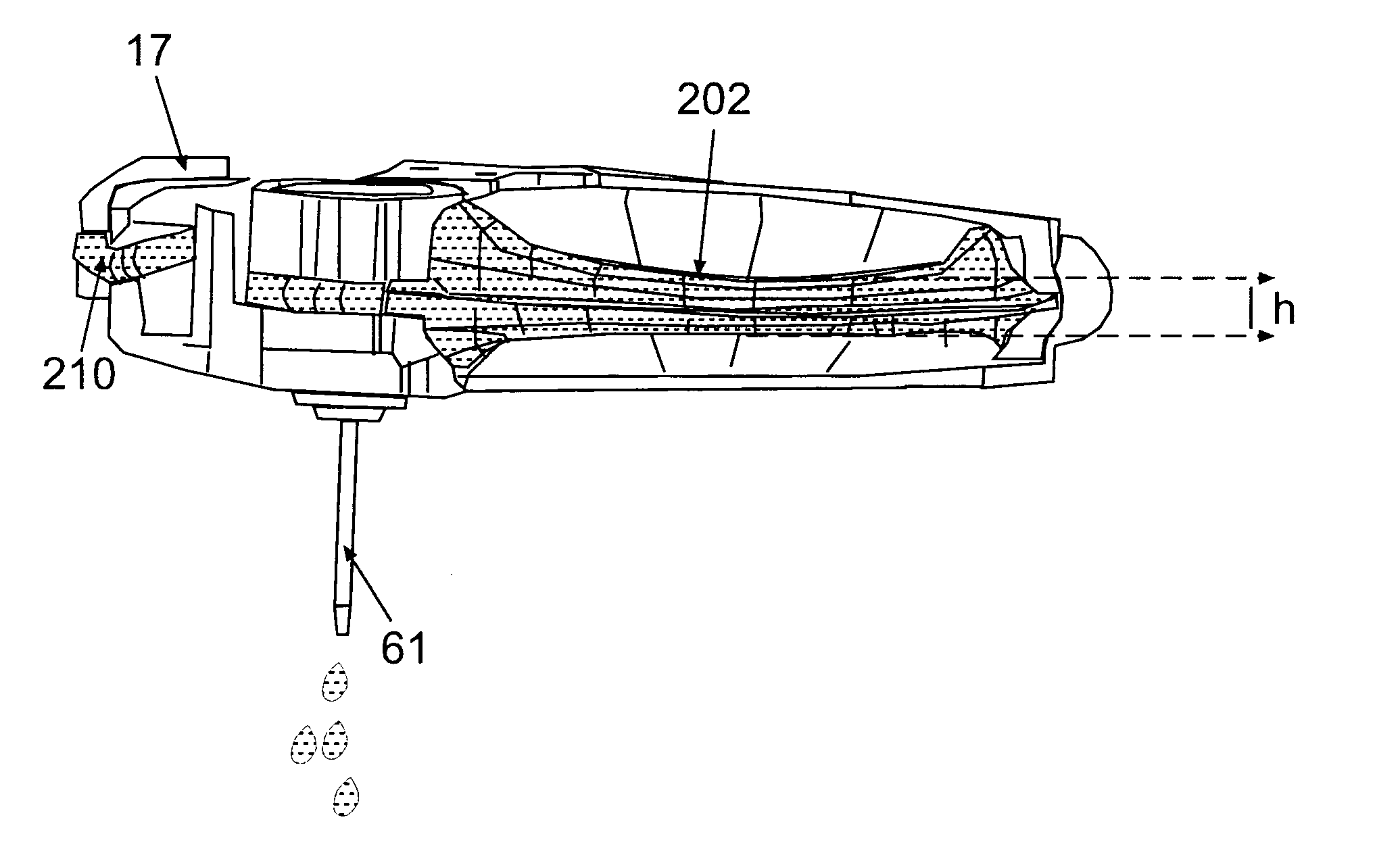
[0082]Disclosed are devices, systems and methods for dispensing fluids, including therapeutic fluids such as, for example, insulin. A fluid dispensing device for delivery of a therapeutic fluid to a user's body includes at least one reservoir to hold the therapeutic fluid, at least one other unit requiring communication with ambient air, at least partly, to operate. Such a device further includes at least one housing defining an interior to retain the at least one reservoir and the at least one other unit. The at least one housing has at least one vent port formed on one or more walls of the at least one housing, that is adapted to direct air into the interior of the at least one housing to maintain pressure equilibrium in the interior of the at least one housing between the air pressure in the interior of the at least one housing and the ambient air pressure outside the at least one housing, and to provide air to the at least one other unit requiring communication with ambient air ...


PUM


Abstract

Disclosed is a fluid dispensing device that includes at least one reservoir to hold the therapeutic fluid, at least one other unit requiring communication with ambient air, at least partly, to operate, and at least one housing defining an interior to retain the at least one reservoir and the at least one other unit. The at least one housing has at least one vent port formed on one or more of its walls. The at least one vent port is adapted to direct or communicate air to maintain pressure equilibrium between the air pressure in the interior of the at least one housing and the ambient air pressure outside the at least one housing, and provide communication with the ambient air to the at least one other unit requiring air to enable operation of the at least one other unit.

Description

CROSS-REFERENCE TO RELATED APPLICATIONS[0001]This application claims priority to provisional U.S. application Ser. No. 60 / 961,382 entitled “Vented Dispensing Device and Method,” filed Jul. 20, 2007, provisional U.S. application Ser. No. 60 / 961,484 entitled “Energy Supply Means for Fluid Dispensing Device,” filed Jul. 20, 2007, and provisional U.S. application Ser. No. 60 / 961,528, entitled “Collapsible Pump Reservoir”, filed Jul. 20, 2007, the contents of all of which are hereby incorporated by reference in their entireties.BACKGROUND OF THE INVENTION[0002]1. Field of the Invention[0003]Embodiments of the present disclosure relate generally to a system, a device and a method for sustained medical infusion of fluids and / or continuous monitoring of body analyte. In some embodiments, a portable infusion patch-like device is provided that is securable (e.g., adherable) to the skin and that optionally may also continuously and / or periodically monitor body analytes. In some embodiments, a ...

Claims


Application Information

Patent Timeline
Patent Type & Authority Applications(United States)
IPC IPC(8): A61M31/00A61B5/00G08B21/00
CPCA61B5/14532A61B5/1486A61M5/14248A61M5/1723A61M5/142A61M2005/14264A61M2205/50A61M2205/82A61M2207/00A61M2005/14204A61M5/14244A61M5/155A61M5/16822A61M2005/14268A61M2205/581A61M2205/582
Inventor YODFAT, OFERNETA, AVRAHAM
Owner ROCHE DIABETES CARE INC
Learn More