Helical Formation for a Conduit

a technology of helical formation and conduit, which is applied in the field of determining the helix angle of a helical formation for a conduit, can solve the problems of little or no information on the physical characteristics or design, the design of helical formations will be ineffective at creating spiral flow, and the effect of preventing the collapse of the blood vessel

Inactive Publication Date: 2010-08-05
TAYSIDE FLOW TECH LTD
View PDF5 Cites 1 Cited by
  • Summary
  • Abstract
  • Description
  • Claims
  • Application Information

AI Technical Summary

Benefits of technology

[0018]The helical formation may effect helical and / or spiral flow in such a fashion as to eliminate or reduce turbulence and / or eliminate or reduce dead flow regions in the conduit. The helix angle to achieve such flow will depend on such factors as diameter of the conduit, longitudinal and rotational velocity of the fluid, and the viscosity and other characteristics of the fluid.
[0020]Alternatively, the conduit may comprise a stent. Stents, for example made of mesh, expanded sheet or tube or wire spring type, are inserted into blood vessels to provide mechanical support and prevent collapse of the blood vessel. A structure according to the present invention could be placed inside or outside the blood vessel to impose, maintain and / or reinforce a flow guiding formation through the blood vessel.

Problems solved by technology

Although the use of helical formations has been proposed as beneficial to fluid flow in conduits by helping to generate spiral fluid flow patterns, there is little or no information on the physical characteristics or design of the helical formation that is required to create a suitable spiral flow pattern.
Clearly, some designs of helical formations will be ineffective at creating spiral flow and others will not create a beneficial spiral flow.
For example, helical formations having a high helix angle may tend to create turbulence rather than spiral flow due.

Method used


Image

  • Helical Formation for a Conduit
  • Helical Formation for a Conduit

Examples


Embodiment Construction

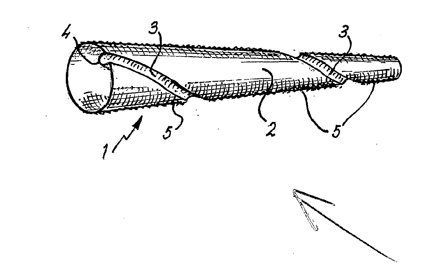
[0027]FIG. 1 is a perspective view of an arterial graft 1 for implantation in the human or animal body. The graft 1 is fabricated from a knitted or woven polyester material. However, any suitable flexible material could be used, such as a spun polyurethane multi-monofilament or a PTFE extrusion.

[0028]The graft 1 is in the form of a tube 2 that has a deformation 3 in the side wall of the tube 2 so that the deformation 3 extends inwardly generally towards the longitudinal axis of the tube 2 to form a helical formation 4 on the internal surface of the tube 2. The tube is also crimped to form circumferential ridges 5 along the length of the tube 2. The circumferential ridges help to provide radial strength to the tube 2 to minimise the risk of the graft collapsing during implantation and subsequently during use.

[0029]The helical formation 4 is intended to promote a rotational flow pattern to blood passing through the graft 1, in use. It is believed that rotational flow has beneficial ef...


PUM


Abstract

A helical formation within a conduit and a method of determining the helix angle of the helical formation are disclosed. The method includes specifying the internal dimensions of the conduit and an intended fluid mass flow through the conduit. The helix angle is determined from the pressure drop and the turbulent kinetic energy for a conduit having the specified internal dimensions and intended fluid mass flow.

Description

CROSS REFERENCE TO RELATED APPLICATIONS[0001]This application claims priority of U.S. patent application Ser. No. 10 / 516,875, with a U.S. filing date of Dec. 3, 2004. U.S. application Ser. No. 10 / 516,875 is a 371 filing of PCT / GB02 / 05646, filed on Dec. 13, 2002 which in turn claims priority of PCT / GB02 / 02580, filed on Jun. 5, 2002.[0002]Furthermore, the underlying concepts, but not necessarily the language, of U.S. patent application Ser. No. 10 / 516,875 are incorporated herein by reference.[0003]If there are any contradictions or inconsistencies in language between this application and the case that have been incorporated by reference that might affect the interpretation of the claims in this case, the claims in this case should be interpreted to be consistent with the language in this case.FIELD OF INVENTION[0004]The invention relates to a method of determining the helix angle of a helical formation for a conduit, and in particular, but not solely, for blood flow tubing.BACKGROUND ...

Claims


Application Information

Patent Timeline
Patent Type & Authority Applications(United States)
IPC IPC(8): A61F2/06F15D1/04F16L11/11A61M1/14A61M5/14F15D1/06
CPCA61F2/06F15D1/065A61F2002/068
Inventor HOUSTON, JOHN GRAEMEHOOD, ROBERT GORDONSTONEBRIDGE, PETER ARNOTHOMSON, ALLAN
Owner TAYSIDE FLOW TECH LTD
Why Eureka
Try Eureka