
Storage Subsystem And Storage System Architecture Performing Storage Virtualization And Method Thereof

a storage subsystem and storage system technology, applied in the field of storage subsystems, can solve the problems of inability to reduce the capacity the inability to change the configuration of a pv and the associated ld/partition, and the large restriction of the utilization of the storage space of the subsystem, so as to improve the elasticity of the use of the raid subsystem

Active Publication Date: 2010-08-05
INFORTREND TECH INC
View PDF3 Cites 66 Cited by
  • Summary
  • Abstract
  • Description
  • Claims
  • Application Information

AI Technical Summary

Benefits of technology

[0011]In accordance with the above reasons, the objective of the present invention is to provide a storage virtualization subsystem, storage system architecture, and method thereof to solve the aforesaid problems of the conventional technologies and to improve the elasticity of usage for RAID subsystem.
[0012]Another objective of the present invention is to provide a storage virtualization subsystem, storage system architecture, and method thereof to avoid resource-wasting problem.

Problems solved by technology

Therefore, once the RAID subsystem presents the PVs to the host, it is difficult to change the configuration of the PVs and the associated LDs / partitions.
Particularly, it is impossible to reduce the capacity of a PV and the associated LD / partition.
Such architecture is subject to some restrictions on the flexibility of the utilization of the RAID subsystem, so the utilization of the storage space of the subsystem is greatly restricted.
After a while, it is found that only 100 GB is needed for the utilization of PV1; while the space required for the utilization of PV2 has been consistently increasing and the 400 GB capacity would be insufficient finally.
In the conventional technologies, because the configuration of PV1 is unchangeable, only 100 GB capacity thereof will be used while the other 300 GB capacity will be left idle and can not be used.
On the contrary, because there is no enough space in PV2, it is necessary to buy some more storage device.
It is a waste of resource.
In addition, under some of the conventional data storage system architectures, either data can not be migrated between disk array subsystems or the system performance of data migration therebetween is quite low, which has a negative influence on the utilization flexibility of the resources of and / or the system performance of the data storage system.
Moreover, under some of the conventional data storage system architectures, although data can not be migrated between the disk array subsystems, the disk array subsystems lack RAID function protection, which is not acceptable to the modern information age having high-level data availability demand.
Therefore, how to increase the flexibility of utilization of a storage subsystem so as to avoid waste of resources is a big issue in the storage industry.

Method used


Image

  • Storage Subsystem And Storage System Architecture Performing Storage Virtualization And Method Thereof
  • Storage Subsystem And Storage System Architecture Performing Storage Virtualization And Method Thereof
  • Storage Subsystem And Storage System Architecture Performing Storage Virtualization And Method Thereof

Examples


Embodiment Construction

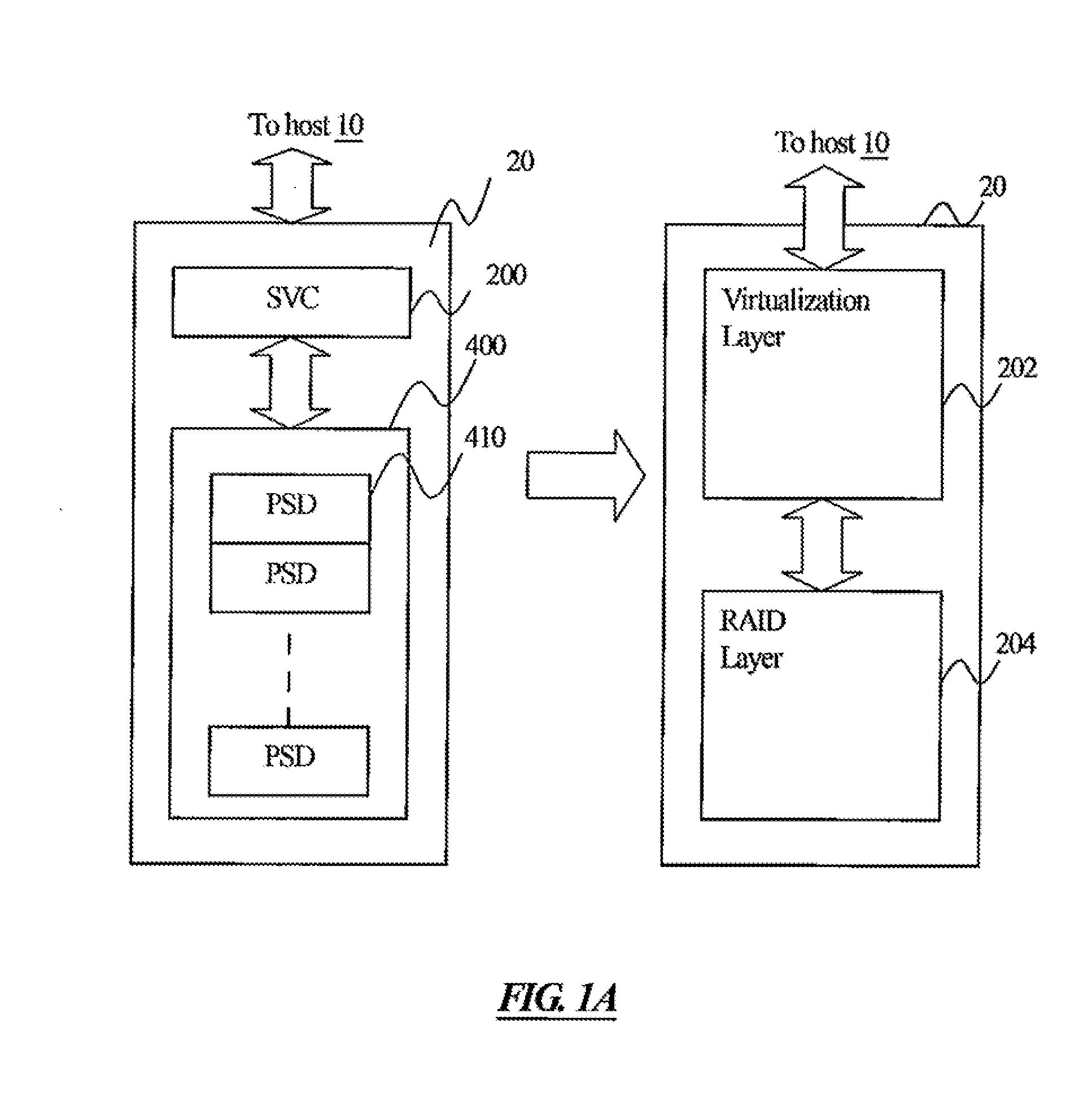
[0089]With reference to FIG. 1A, which is a data storage system architecture 1 (abbreviated storage system architecture) in accordance with an embodiment of the present invention. The storage system architecture 1 comprises a host 10 and a redundant array of independent disks subsystem 20 (abbreviated RAID subsystem) connected through a communication channel. The RAID subsystem 20 comprises a storage virtualization controller (SVC) 200 and a PSD array 400 having a plurality of physical storage devices 410 (PSD). The PSDs 410 can be any of the following storage devices: HDD, CD, VCD, DVD, TAPE, SSD, Flash Memory, and EEPROM. In accordance with another embodiment of the present invention; a RAID subsystem includes a plurality of storage virtualization controllers 200, which are redundantly configured. When one of the storage virtualization controllers 200 fails, another RAID controller 200 may still work normally and take over the tasks of the failed controller 200.

[0090]According to ...


PUM


Abstract

A method for generating a virtual volume (VV) in a storage system architecture. The architecture comprises a host and one or more disk array subsystems. Each subsystem comprises a storage controller. One or more of the subsystems comprises a physical storage device (PSD) array. The method comprises the following steps: mapping the PSD array into a plurality of media extents (MEs), each of the MEs comprises a plurality of sections; providing a virtual pool (VP) to implement a section cross-referencing function, wherein a section index (SI) of each of the sections contained in the VP is defined by the VP to cross-reference VP sections to physical ME locations; providing a conversion method or procedure or function for mapping VP capacity into to a VV; and presenting the VV to the host. A storage subsystem and a storage system architecture performing the method are also provided.

Description

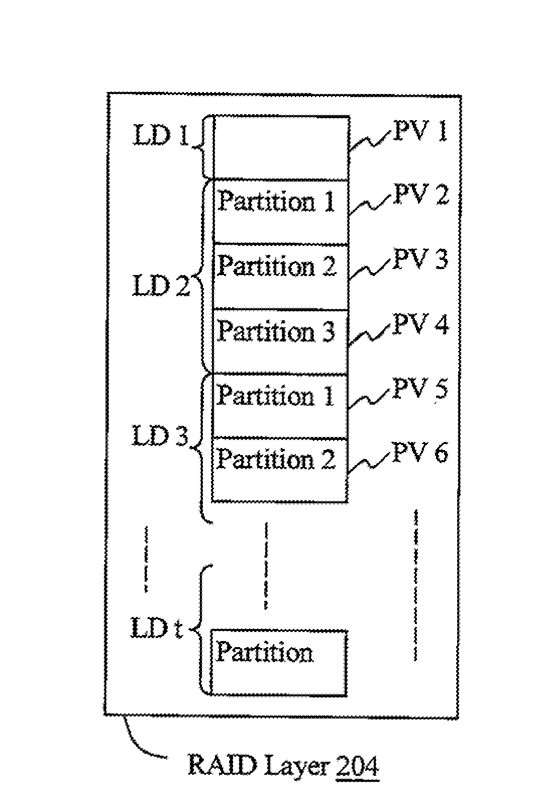
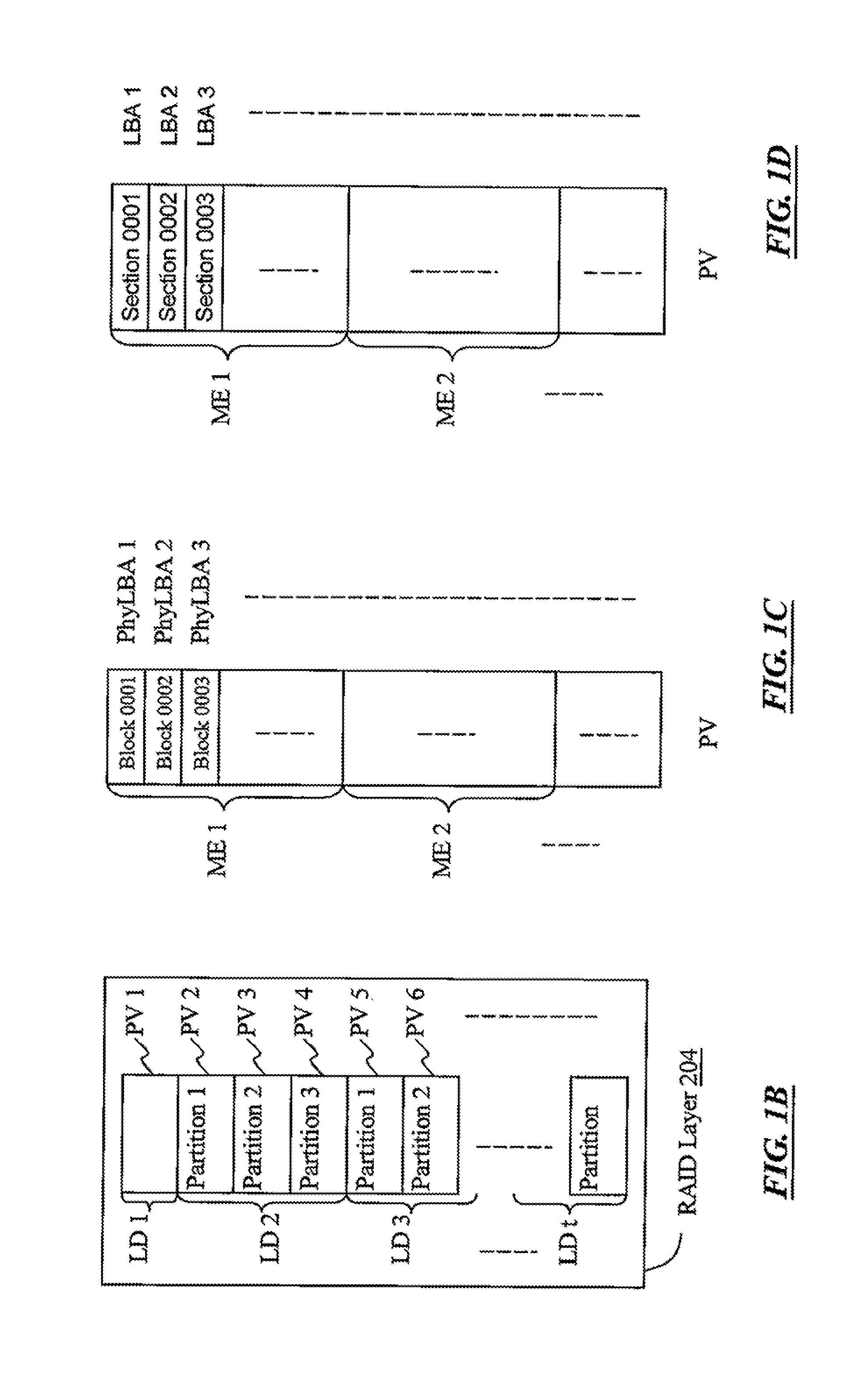
RELATED APPLICATIONS[0001]This application claims priorities to U.S. Provisional Application Ser. Nos. 61 / 146,659 and 61 / 185,578, respectively filed Jan. 23, 2009 and Jun. 9, 2009, which are herein incorporated by reference.BACKGROUND OF THE INVENTION[0002]1. Field of the Invention[0003]The present invention relates to a method for performing storage virtualization; and more particularly, relates to a method for performing storage virtualization which may flexibly expand the storage capacity.[0004]2. Descriptions of the Related Art[0005]In the conventional technologies, the logical drives (LDs) / partitions mapped from a RAID subsystem is presented as physical volumes (PVs) on the host channel for the host to access. The host uses the LBA of the LDs / partitions to access the PVs. Therefore, once the RAID subsystem presents the PVs to the host, it is difficult to change the configuration of the PVs and the associated LDs / partitions. Particularly, it is impossible to reduce the capacity ...

Claims


Application Information

Patent Timeline
IPC IPC(8): G06F12/00G06F3/00G06F12/16G06F11/08
CPCG06F3/0605G06F3/0631G06F12/0808G06F3/0689G06F3/0665G06F3/0659G06F3/0683G06F12/0891G06F2212/1004G06F2212/152G06F2212/262
Inventor SCHNAPP, MICHAEL GORDONFANG, CHING-HUA
Owner INFORTREND TECH INC
Learn More