Devices for cleaning endotracheal tubes

a technology for endotracheal tubes and cleaning devices, which is applied in the direction of respirators, applications, catheters, etc., can solve the problems of increasing the cost of hospitalization, increasing the cost of treating such conditions, and increasing the expected mortality of affected patients, so as to prevent material buildup, prevent the effect of leaking, and perform the cleaning quickly

Active Publication Date: 2010-08-12
AVENT INC
View PDF38 Cites 75 Cited by
  • Summary
  • Abstract
  • Description
  • Claims
  • Application Information

AI Technical Summary

Benefits of technology

[0009]There remains a need for systems, methods and devices for the cleaning of endotracheal tubes that are effective and efficient so that the tube cleanings can be reasonably carried out on a regular and preventative basis, rather than only when a particular problem arises. There also remains a need for systems, methods and devices for the cleaning of endotracheal tubes that prevent the build up of materials, perform the cleaning quickly, and that permit sufficient airflow through the endotracheal tube during use.

Problems solved by technology

Further, ventilator-acquired pneumonia (VAP) is the leading cause of morbidity and mortality in the intensive care unit (ICU), and once present, can double the expected mortality for affected patients.
In certain circumstances, VAP significantly increases the cost of hospitalization.
Tracheostomy can further increase the cost of dealing with such conditions.
Because VAP is so prevalent for intubated patients, this could vastly increase the cost to health care providers.
Frequently, it is not practical or clinically acceptable to change out the endotracheal tube when there is a buildup of biofilm in order to remove the endotracheal tube for cleaning.
Removal and reinsertion of the endotracheal tube can be uncomfortable for the patient, can cause injury to the native airway, and can put reliable control of the airway at risk.
Biofilm can accumulate over time to a level that impairs ventilation by significantly reducing the cross-sectional area of the lumen of the endotracheal tube.
Progressive airway occlusion within the endotracheal tube can make weaning and extubating the patient difficult or impossible, and may lead to the need for a tracheostomy.

Method used


Image

  • Devices for cleaning endotracheal tubes
  • Devices for cleaning endotracheal tubes
  • Devices for cleaning endotracheal tubes

Examples


Embodiment Construction

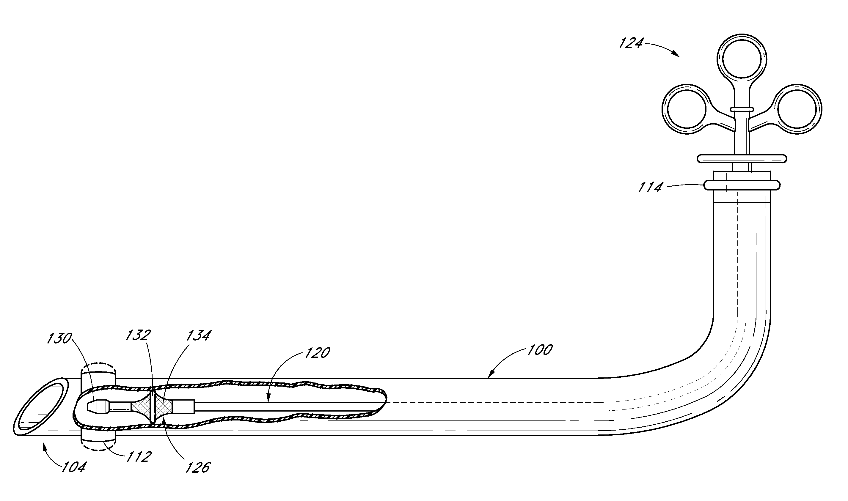
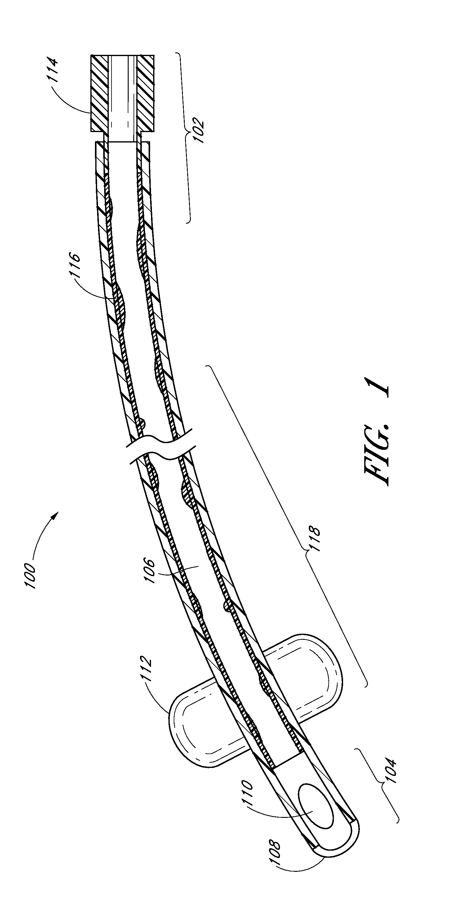
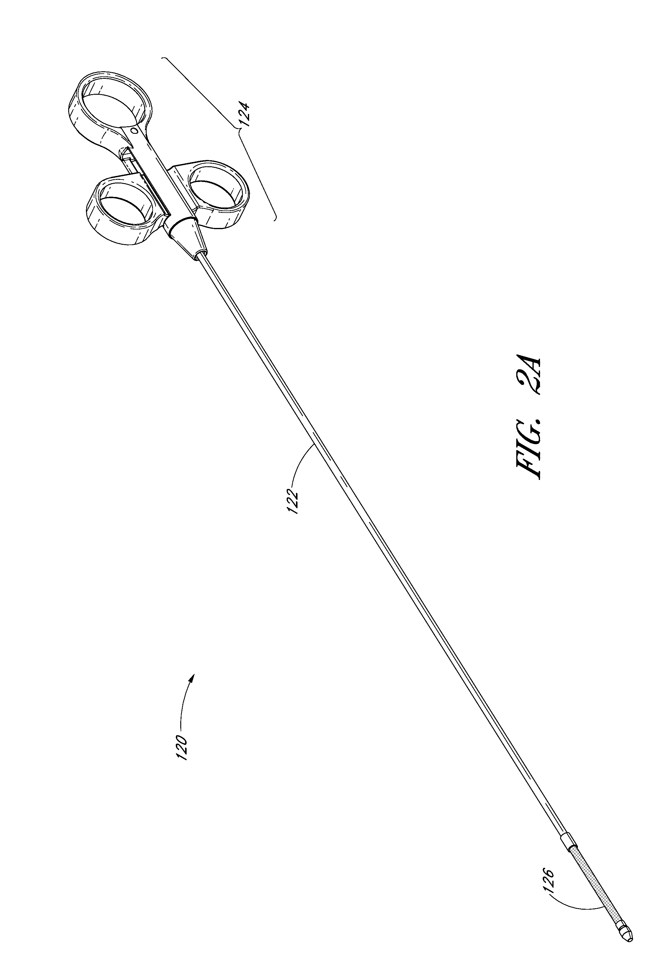
[0090]The discussion and the figures illustrated and referenced herein describe various embodiments of a body-inserted tube cleaning system and device, as well as methods related thereto. A number of these embodiments of tube cleaning systems, devices and methods are particularly well suited to remove biofilm from an interior surface of an endotracheal tube. However, the various devices, systems, methods and other features of the embodiments disclosed herein may be utilized or applied to other types of apparatuses, systems, procedures, and / or methods, whether medically-related or not. For example, the embodiments disclosed herein can be utilized for, but are not limited to, cleaning bronchoscopes, chest drainage tubes, gastrostomy drainage tubes, abdominal drainage tubes, other body drainage tubes, feeding tubes, endoscopes, percutaneous dialysis catheters, and any other percutaneous or per os catheters or body-inserted tubes. In addition, as discussed in greater detail herein, the ...


PUM


Abstract

Systems, devices, and methods are disclosed for the cleaning of an endotracheal tube while a patient is being supported by a ventilator connected to the endotracheal tube. According to some embodiments, a mechanically-actuated non-inflatable cleaning device for scraping debris (e.g., biofilm) from an interior wall of an endotracheal tube is provided. In one embodiment, the cleaning device comprises an elongated member having a proximal end and a distal end and a mechanically-expandable scaffold positioned along the distal end of the elongated member. In one embodiment, the mechanically-expandable scaffold comprises one or more removal members configured to engage an interior surface of an endotracheal tube when the scaffold is in a radially-expanded position and to remove debris from the interior surface of the endotracheal tube when the device is withdrawn from the endotracheal tube.

Description

CROSS REFERENCE TO RELATED APPLICATIONS[0001]This application is a continuation application of U.S. patent application Ser. No. 12 / 701,421, filed Feb. 5, 2010, which claims the priority benefit under 35 U.S.C. §119(e) of U.S. Provisional Application No. 61 / 150,456, filed Feb. 6, 2009, the entireties of both of which are hereby incorporated by reference herein.BACKGROUND[0002]1. Field[0003]This application relates generally to the cleaning of body-inserted tubes and, more specifically, to devices, systems, and methods for removing fluids, secretions and / or other materials from a lumen of an endotracheal tube.[0004]2. Description of the Related Art[0005]An endotracheal tube is used in patient care to provide a clear airway through the mouth, pharynx, and trachea into the tracheobronchial tree. Use of an endotracheal tube is appropriate when the integrity of the airway is, or may become, challenged due to trauma or pathology, or if a patient cannot otherwise breathe unaided. Often the ...

Claims


Application Information

Patent Timeline
Patent Type & Authority Applications(United States)
IPC IPC(8): B08B9/04A61M16/00
CPCA61B1/126A61B1/267A61B19/34A61B2019/343A61M16/04A61M2209/10A61M16/0463A61M2202/203A61B1/122A61B1/2676A61M16/0434A61M16/0833A61M16/0486A61B90/70A61B2090/701A61B1/06B08B9/0436A61B1/00082A61B1/00096A61M25/0097A61M25/1002A61M39/16
Inventor VAZALES, BRAD E.BERTOLERO, ARTHURWATSON, KENGRACY, JAMES M.COLWELL, CLIFTON P.BERKY, CRAIG B.DAVIDNER, ALAN
Owner AVENT INC
Why Eureka
Try Eureka