In-line inspection tool for pipeline integrity testing

Active Publication Date: 2010-08-12
WEATHERFORD TECH HLDG LLC
View PDF11 Cites 37 Cited by
  • Summary
  • Abstract
  • Description
  • Claims
  • Application Information

AI Technical Summary

Benefits of technology

[0008]Provided herein is an electromagnetic acoustic transducer (EMAT) in-line pipeline inspection tool that provides high sensitivity, low interference and

Problems solved by technology

Pipeline defects may include loss of coatings, corrosion, stress corrosion cracking (SCC), and circumferential and axial flaws.
Defects such as corrosion or cracks in the pipeline walls create detectable reflections in the generated shear waves.
Moreover, the long time interval between emissions of ultrasound waves as the tool is moving through the pipeline establishes a relatively long distance along the pipeline axis between where ultrasound waves are generated and where crack-like defects can be detected thus limiting the in-line inspection length resolution along the axis of the pipe.
The main disadvantage of this method is that in order to cover the whole circumference of the pipe there is a need for at least two rows of EM

Method used


Image

  • In-line inspection tool for pipeline integrity testing
  • In-line inspection tool for pipeline integrity testing
  • In-line inspection tool for pipeline integrity testing

Examples


example 1

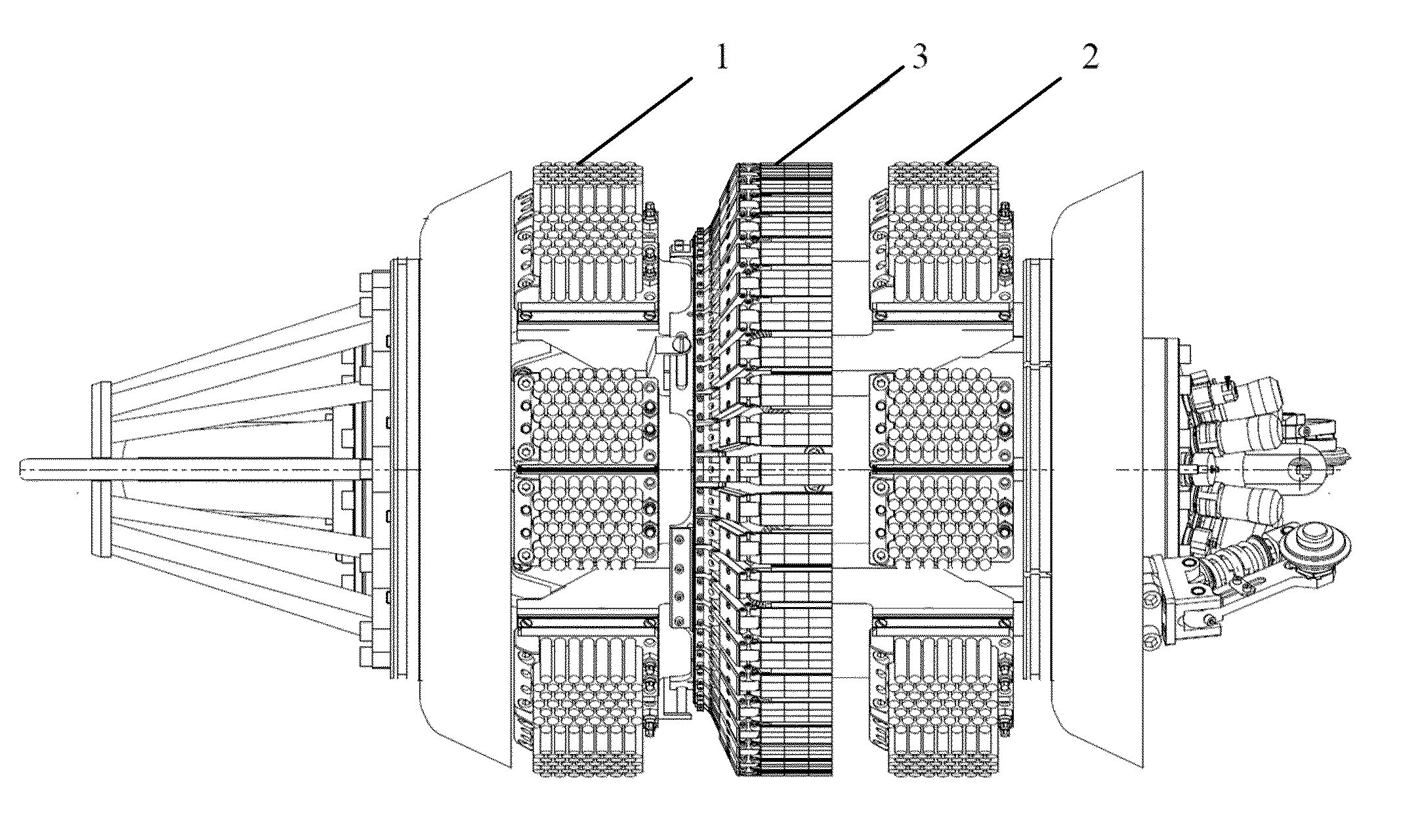
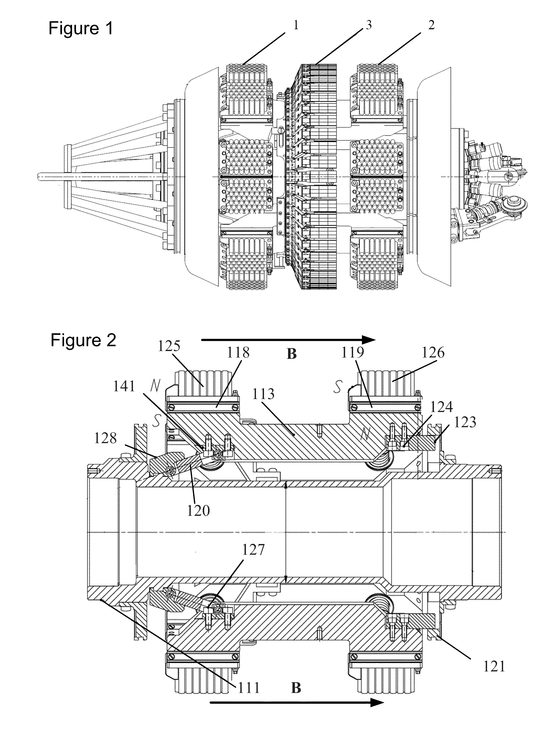
[0039]In one embodiment of an in-line inspection tool, the tool includes a body with axial symmetry that is provided with electronics for tool control and processing of measurement data. The tool includes pipe wall magnetization elements fitted on the body. As depicted in FIG. 1, the magnetization elements include belts of magnets (1) and (2) of opposite polarity wherein the poles of opposite polarity face the internal surface of a pipe. An EMAT belt (3) is installed in-between the belts of magnets of opposite polarity. The magnets (1) and (2) and EMAT array (3) are adapted to pass lightly against the internal surface of a pipeline while the inspection tool travels through the pipeline.

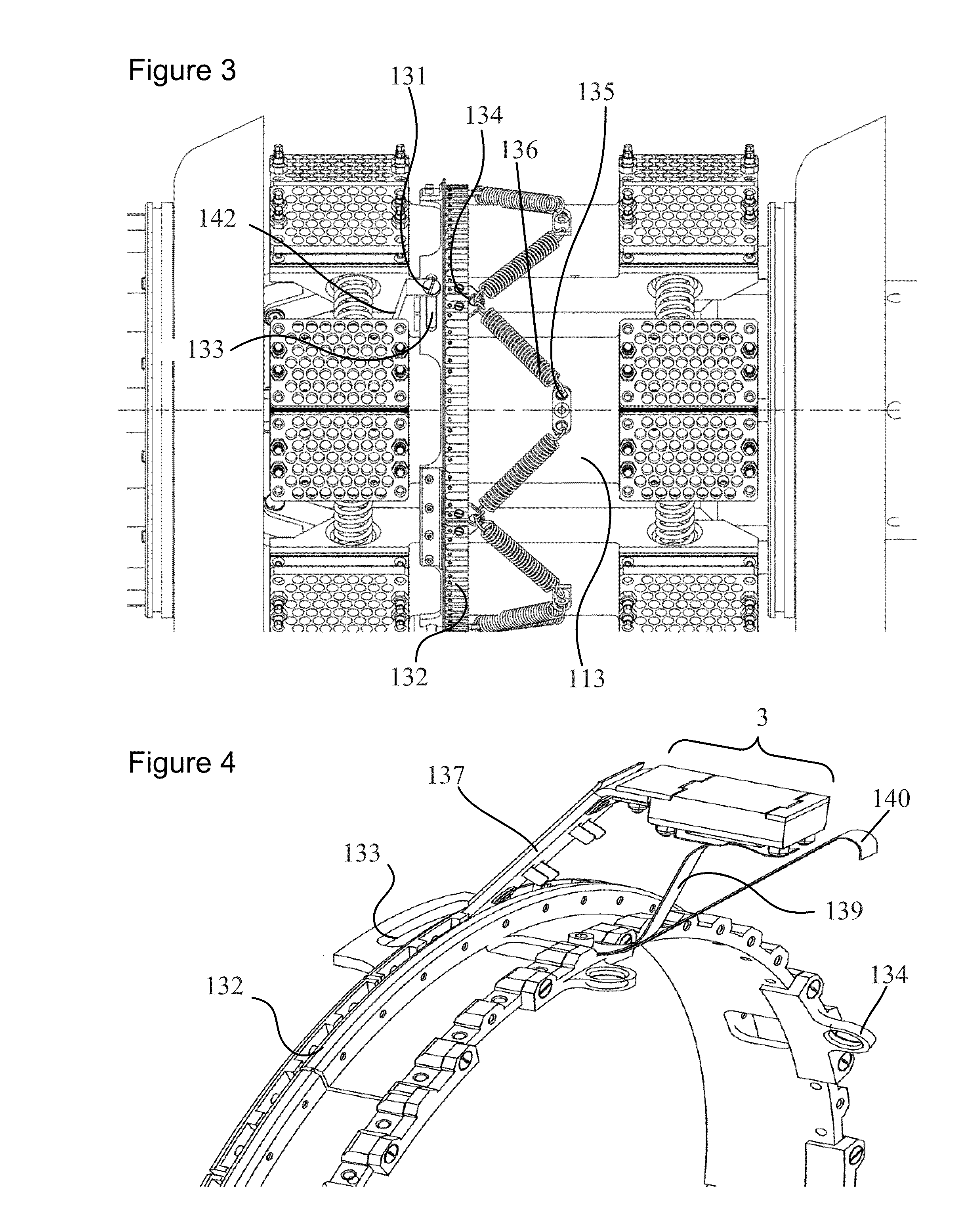
[0040]FIG. 2 depicts an expanded cross-section of a portion of the tool depicted in FIG. 1. The tool contains the housing (111) with axial symmetry. Ferromagnetic bars (113) are installed on the housing (111) around the axis of the housing. An electronic measurement system is installed in the housing ...

example 2

[0058]In an alternative embodiment, an in-line inspection tool for inspecting pipeline wall for defects is provided that includes the body with axial symmetry and means of tool control and processing of measurement data. The tool further includes a pipe wall magnetization element fitted on the body that includes pairs of magnets facing the internal surface of a pipe by the poles of opposite polarity as well as EMATs installed in-between said poles. The magnetization element and the EMATs are adapted to come in close approximation to the internal surface of the pipeline and may press lightly against the internal surface or depart slightly from the surface while the inspection tool travels through a pipeline. The EMAT are arranged in EMAT clusters wherein each cluster includes two receiving EMATs and one transmitting EMAT located between said receiving EMATs. The transmitting EMAT is capable of generating ultrasound waves in pipeline wall in two opposite directions, while the receivin...


PUM


Abstract

Apparatus and methods are provided for non-destructive in-line pipeline inspection utilizing electromagnetic acoustic transducer (EMAT) technology wherein the EMATs are arrayed circumferentially in a belt around the body of the tool and wherein the EMAT belt includes a plurality of EMAT clusters, each cluster including a transmitting EMAT essentially sandwiched between a pair of receiving EMATs. The EMAT arrangement enables a single receiving EMAT to monitor both the test signal and the returning reflection from the pipewall defect thus providing each signal with its own internal reference. The number of transducers and their positional relationship limits the generation of interference signals, is conservative in power consumption, and provides a tool having enhanced negotiability through the pipeline.

Description

CROSS REFERENCE TO RELATED APPLICATIONS[0001]This application claims priority based on U.S. Provisional Application Ser. No. 61 / 150,884 filed Feb. 9, 2009, which is incorporated herein by reference in its entirety.FIELD OF THE INVENTION[0002]This invention relates to in-line inspection of pipelines for structural and / or coating defects and more particularly to inspection of electrically conductive pipes employing in-line inspection pigs that utilize electromagnetic acoustic transducer technology.BACKGROUND OF THE INVENTION[0003]Without limiting the scope of the invention, its background is described in connection with novel apparatus and methods for non-destructive pipeline inspection. Pipelines require periodic testing to insure the absence of defects that may ultimately result in loss of product or catastrophic pipeline failure. Pipeline defects may include loss of coatings, corrosion, stress corrosion cracking (SCC), and circumferential and axial flaws. Non-destructive testing (N...

Claims


Application Information

Patent Timeline
IPC IPC(8): G01N29/04
CPCG01N29/225G01N2291/2636G01N29/2412
Inventor GANIN, YEVGENIY VLADIMIROVICH
Owner WEATHERFORD TECH HLDG LLC
Why Eureka
Try Eureka