Distributed acoustic sensing with fiber bragg gratings

a technology fiber bragg grating, which is applied in the field of distributed acoustic sensing with fiber bragg grating, can solve the problems of limited resolution of conventional systems, large number relatively high acquisition, deployment and maintenance costs of large numbers of geophones or hydrophones, etc., and achieves the effect of increasing the sensitivity of the cable to strain

Active Publication Date: 2010-08-12
SHELL USA INC
View PDF20 Cites 88 Cited by
  • Summary
  • Abstract
  • Description
  • Claims
  • Application Information

AI Technical Summary

Benefits of technology

[0017]A portion of the cable is wrapped around a tubular in a well or may include loops or curves that increase the sensitivity of the cable to strain.

Problems solved by technology

In instances where the sensors are placed in a borehole, fewer sensors are used, and the information available is correspondingly limited.
First, it is relatively expensive to acquire, deploy and maintain the large numbers of geophones or hydrophones that are needed in order to provide the desired level of resolution for the time periods that are typically involved, which may be on the order of years.
Second, the resolution of conventional systems is limited by the number and placement of the acoustic receivers.
Current DAS systems provide spatial resolution on the order of 1-10 m. This insufficient in many situations, including in-flow monitoring applications, where relevant events could be very localized (<1 m).
The source of this limitation is due to the tradeoff between the length of the pulse (or spatial resolution) and measurement sensitivity.

Method used


Image

  • Distributed acoustic sensing with fiber bragg gratings
  • Distributed acoustic sensing with fiber bragg gratings
  • Distributed acoustic sensing with fiber bragg gratings

Examples


Embodiment Construction

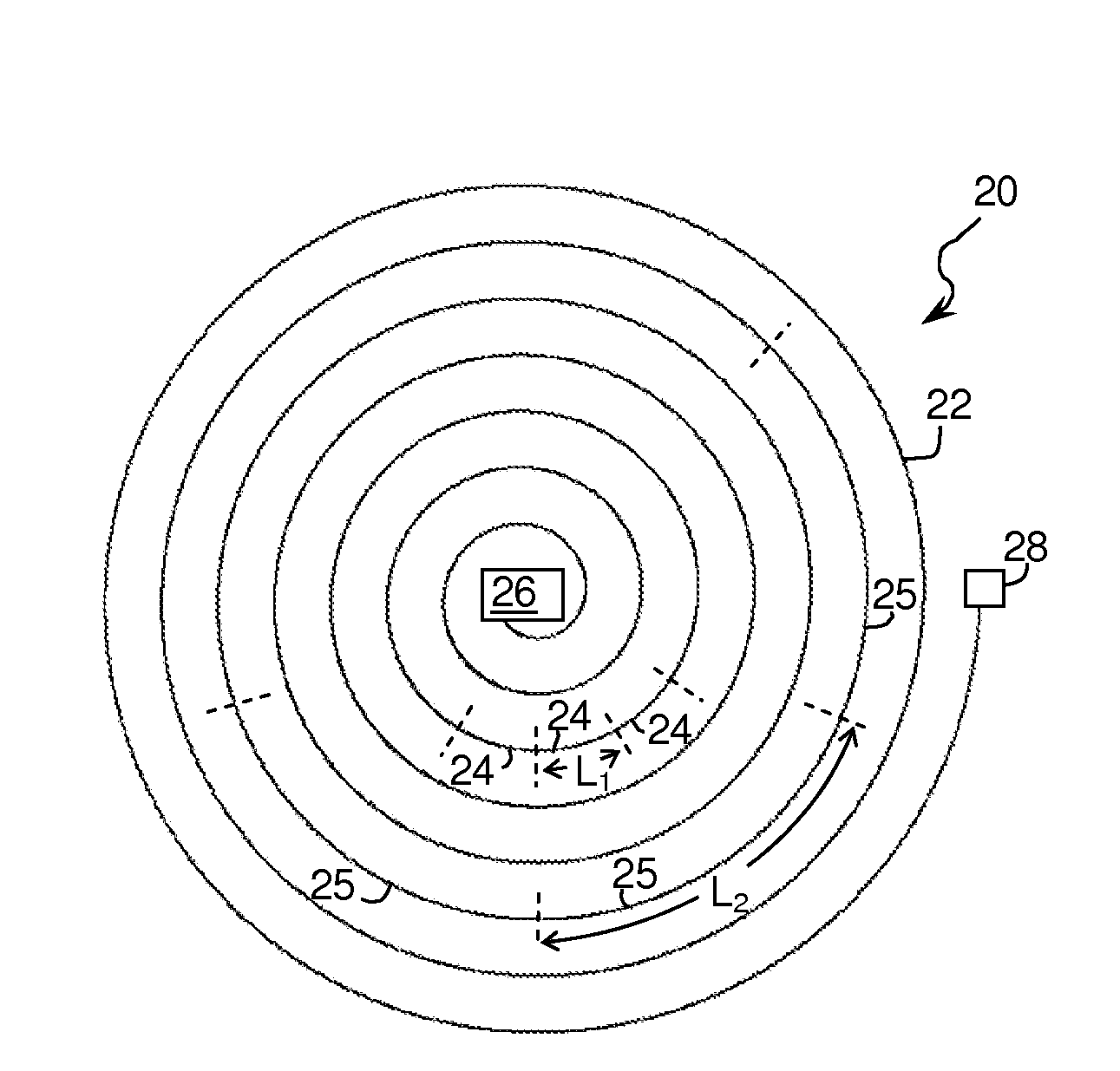
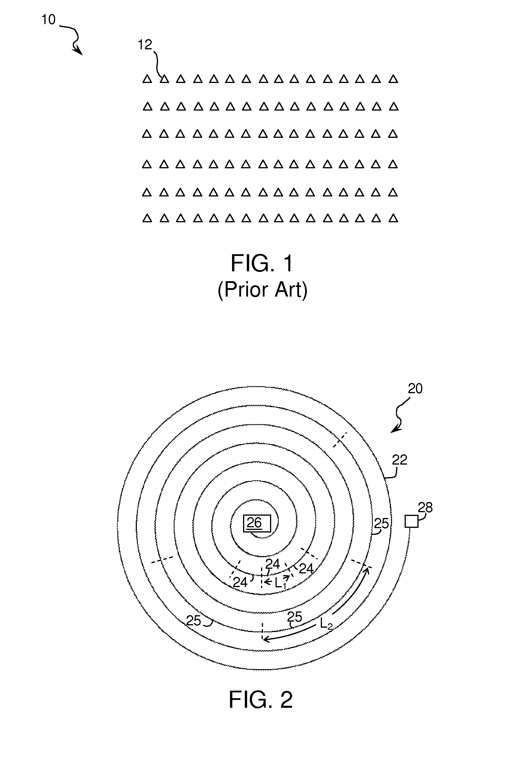
[0026]Referring initially to FIG. 1, an array 10 of conventional acoustic sensors 12 may be deployed as shown. The number of sensors available to cover the desired area is typically limited by cost; once the number of available sensors is established, the sensors are deployed. For on-shore applications, the sensors may be deployed manually, such as by using a GPS system to place each sensor in a desired location, or they may be installed at the bottom of purposely drilled shallow boreholes. For offshore applications, the sensors, referred to as Ocean Bottom Seismometers (OBS) may be deployed by remotely operated vehicle (ROV) and placed on the seabed at desired locations, or they may be deployed in cabled configurations with fixed inter-sensor spacings in via Ocean Bottom Cables (OBC) laid on the seabed.

[0027]Regardless of the mode or manner of deployment, it is frequently desired to acquire data having more resolution than is available. Without additional sensors, it is impossible ...


PUM


Abstract

A method for obtaining information about a subsurface formation from acoustic signals that contain information about to the subsurface formation, comprises: providing a fiber optic having a proximal end and a remote end, with the proximal end being coupled to a light source and a proximal photodetector, wherein said fiber optic cable includes randomly spaced impurities and selectively placed Bragg gratings and wherein the fiber optic cable is acoustically coupled to the subsurface formation so as to allow the acoustic signals to affect the physical status of at least one grating: transmitting at least one light pulse into the cable; receiving at the photodetector a first light signal indicative of the physical status of at least one first section of the cable, and outputting at least one item of information to a display.

Description

RELATED CASES[0001]This case claims priority to U.S. provisional application 61 / 150,842, filed Feb. 9, 2009 and entitled “Method Of Detecting Fluid In-Flows Downhole,” which is incorporated herein by reference.FIELD OF THE INVENTION[0002]The invention relates to a method of increasing the spatial resolution of an optical sensing system by including fiber Bragg gratings in portions of the optical fiber.BACKGROUND OF THE INVENTION[0003]Seismic surveys are useful for studying subsurface formations in many contexts, including the monitoring of subsurface hydrocarbon reservoirs and the tracking of fluids, e.g. oil, gas, or water, as they flow through the subsurface strata. One type of areal monitoring that is gaining in importance is the ability to track CO2 that has been injected as part of carbon capture and sequestration (CCS) projects. Also of interest in the context of subsurface monitoring are the various fluids that are used for enhanced oil recovery (EOR), hydrocarbon saturation,...

Claims


Application Information

Patent Timeline
Patent Type & Authority Applications(United States)
IPC IPC(8): G01V5/00
CPCG01V8/16G01V1/16G01V1/46G01V2210/1234G01V2210/1429G01V1/226G01D5/35316G01D5/35361G01V1/22
Inventor PEARCE, JEREMIAH GLENRAMBOW, FREDERICK HENRY KREISLERDRIA, DENNIS EDWARD
Owner SHELL USA INC
Why Eureka
Try Eureka