Humidifier, filter unit and rotation drive structure

a technology of rotating drive structure and humidifier, which is applied in the direction of centrifuges, gearing, separation processes, etc., can solve the problems of increasing the size of humidifier, reducing the water absorption capacity of humidifier, and complicated structure for rotating the humidifier in the respective directions, so as to prevent unwanted water absorption of the humidifier, and simple structure

Active Publication Date: 2010-08-12
SHARP KK
View PDF6 Cites 25 Cited by
  • Summary
  • Abstract
  • Description
  • Claims
  • Application Information

AI Technical Summary

Benefits of technology

[0150]According to the humidifier and the filter unit of the present invention, the absorption / non-absorption of the filter unit can be switched merely through the rotation in the circumferential direction of the filter unit with the disc-shaped filter unit disposed in a vertical orientation and with the filter unit immersed in water. In other words, the problem of the unwanted water absorption of the filter unit can be prevented with a simple structure.
[0151]According to the humidifier and the filter unit of the present invention, the absorption / non-absorption of the filter unit can be switched by switching the immersion / non-immersion of the filter main body merely through the rotation in the circumferential direction of the filter unit with the disc-shaped filter unit disposed in a vertical orientation and with the filter unit immersed in the water. In other words, the problem of the unwanted water absorption of the filter unit can be prevented with a simple structure.
[0152]According to the humidifier and the rotation drive structure of the present invention, since the rotating body for holding the filter main body is rotatively in contact with the roller for rotating the rotating body, the rotating body and the roller can be easily separated from each other, resulting in attaining an effect that the filter main body can be exchanged or cleaned for maintenance. Furthermore, since the roller is disposed substantially directly above the rotating body, the roller applies the substantially directly downward pressure to the rotating body, and thus, the pressure is uniformly applied to the rotating body. As a result, an effect that the roller transfers a stable turning force to the rotating body for making the rotating body stably rotate is exhibited. Furthermore, since the rotating body is rotatively in contact with the roller substantially directly above the rotating body, when the rotating body is moved horizontally, it can be brought into rotative contact with the roller even when the rotating body is slightly shifted in the horizontal direction. Moreover, when the rotating body is brought into rotative contact with the roller, the rotating body is horizontally moved, and therefore, an effect that variation in contact between the roller and the rotating body is reduced is exhibited.

Problems solved by technology

Particularly when a filter is used for a long period of time, water-soluble impurities (namely, scales), such as calcium and magnesium, included in the water absorbed by the filter are deposited and adhered onto the filter, which causes a problem that the water absorbability of the filter is degraded.
Therefore, the structure for rotating the filter in the respective directions is very complicated.
As a result, there arises a problem that the humidifier is increased in its size.
Nevertheless, if a filter is allowed to be immersed in water without switching the immersion / non-immersion, there arise a problem of adhesion of scales and growth of mold on the filter.
Moreover, in the case where air is desired to be simply sent without performing humidification, even when the rotation of the filter is stopped, the filter placed in an immersion state continuously absorbs water, and hence, the sent air passes through the filter and there arises a problem that the thus moistened air is discharged from the humidifier.
For this purpose, however, the humidifier should be provided with two different air ducts and means for switching the air ducts, which makes the structure of the humidifier complicated.
Furthermore, in order to provide the two air ducts without increasing the size of the humidifier, each air duct tends to be formed in a complicated shape, and as a result, noise caused by air passing through the air ducts tends to be large.
The filter on which the dust or the incrustations are adhered cannot sufficiently transmit air or cannot sufficiently suck the water reserved in the water tank, resulting in degrading the performance of the humidifier.
In the humidifier disclosed in Japanese Patent Application Laid-Open No. 2003-302077, however, the filter is directly connected to a gear motor for the rotation, and hence, a user cannot easily attach / remove the filter.
Therefore, maintenance such as exchange or cleaning of the filter cannot be performed.
Therefore, the filter unit does not absorb water any more, and furthermore, the filter unit is dried up due to drop, evaporation and the like of the water having been absorbed by the filter unit.
Therefore, at least one of the ends having a larger diameter is never easily supported by one of the bearings for supporting the end having a smaller diameter (specifically, for example, the end having the larger diameter does not fit in the bearing or even when it is forcedly fit, the rotation shaft part does not smoothly rotate).
Therefore, the user may set the filter unit in a wrong direction, which causes a problem that the detector cannot detect the detection target.
Therefore, even when air passes through the filter unit including the dried filter main body by the fan, the air passing through the filter unit does not absorb moisture, and hence, moistened air is never sent to outside the humidifier.
However, it is difficult to accurately stop the rotating filter unit with the center in the circumferential direction of the non immersion region 91b positioned directly below, and the filter unit may be stopped in a state, for example, where the center in the circumferential direction of the non immersion region 91b is shifted in the rotation direction (or in the direction opposite to the rotation) from the position directly below.
On the other hand, in the filter unit including the filter main body 92 of FIG. 22, although the filter main body 92 can be kept in a non-immersion state even when the positional shift is caused in the stop position of the filter unit, it has the problem that the filter main body 92 does not have a shape and an area suitable for attaining a sufficient amount of absorbed water.
On the contrary, a portion of the frame where the watertight section is not provided does not prevent water from entering inside the frame.
Therefore, at least the end having a larger diameter is never easily supported by one of the bearings for supporting the end having a smaller diameter (specifically, for example, the end having the larger diameter does not fit in the bearing or even when it is forcedly fit, the rotation shaft part does not smoothly rotate).
Therefore, the user may set the filter unit in a wrong direction, which causes a problem that the detector cannot detect the detection target.

Method used


Image

  • Humidifier, filter unit and rotation drive structure
  • Humidifier, filter unit and rotation drive structure
  • Humidifier, filter unit and rotation drive structure

Examples


embodiment 1

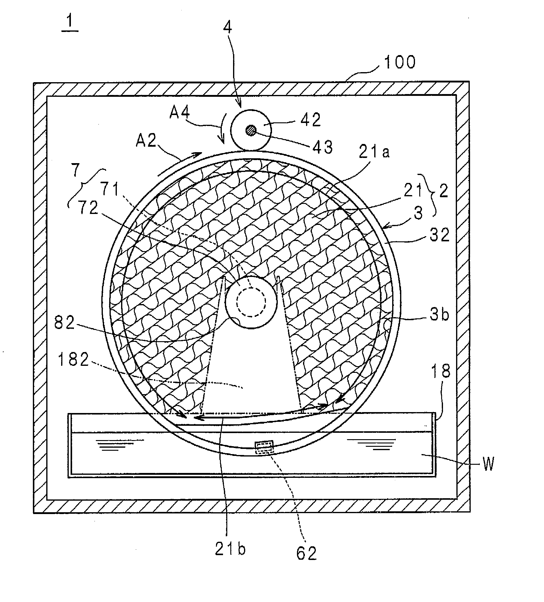
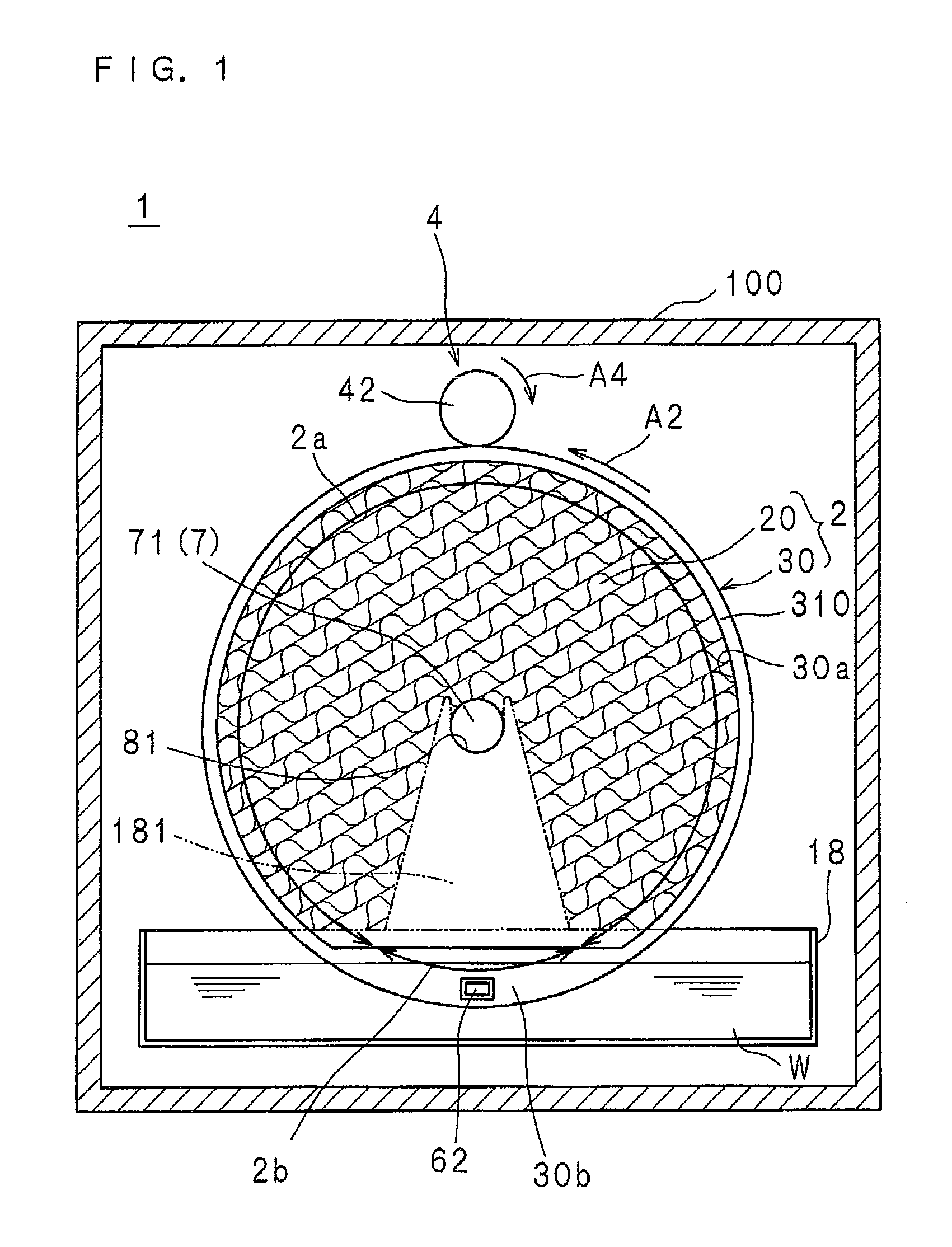
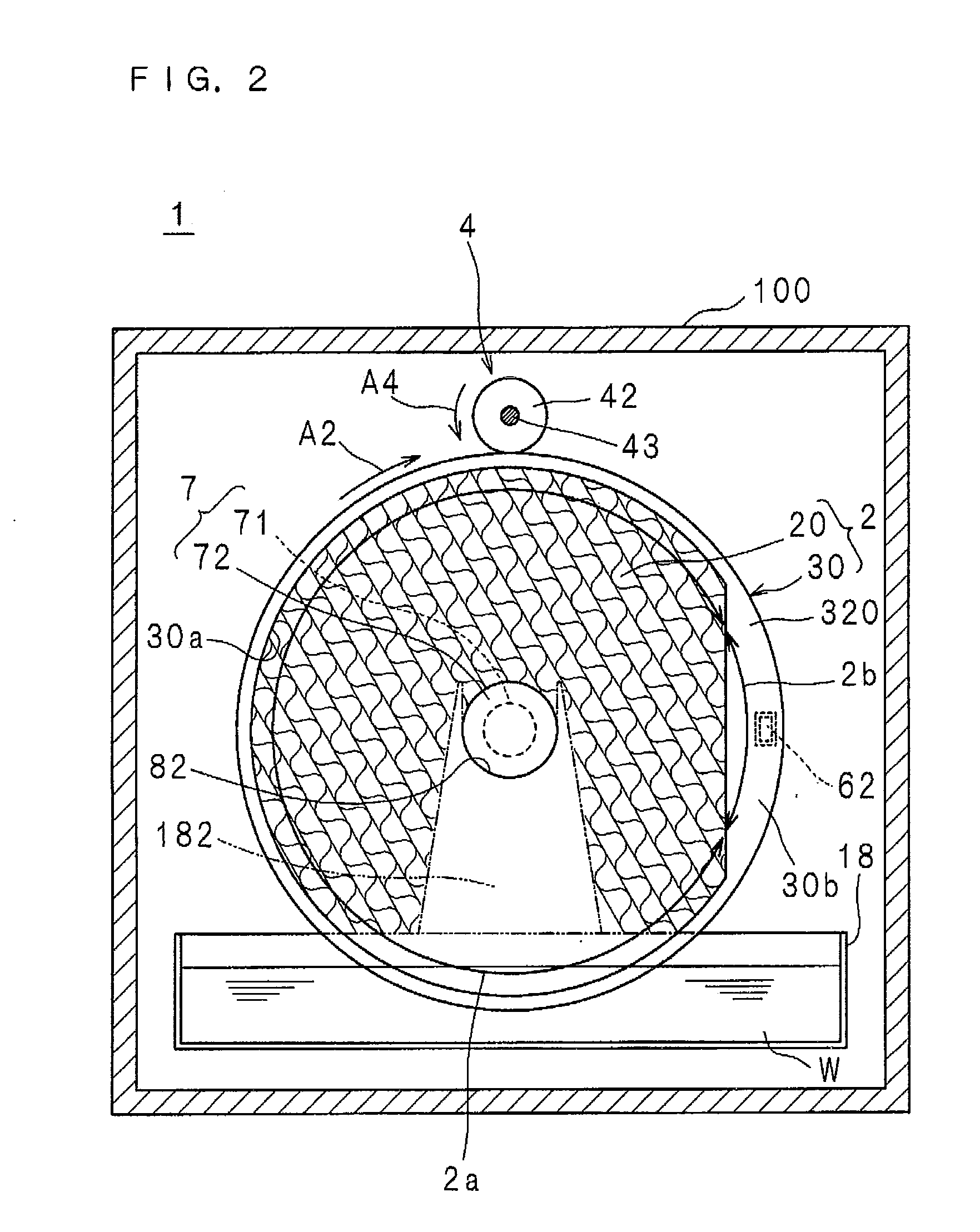
[0180]FIG. 1 is a schematic rear view illustrating a one face side of a filter unit included in a humidifier according to Embodiment 1 of the invention, and FIG. 2 is a schematic front view illustrating the other face side of the filter unit. Also, FIG. 3 is a schematic side view illustrating the internal structure of the humidifier, and FIG. 4 is a block diagram illustrating the structure of a principal part of the humidifier.

[0181]In these drawings, a reference numeral 1 denotes a humidifier, and the humidifier 1 includes, as illustrated in FIGS. 1 through 4, a housing 100, a CPU 10, a ROM 11, a RAM 12, an EEPROM 13, a display section 14, an operation section 15, a humidity sensor 16, an air cleaning filter 17, a water tank 18, a filter unit 2 having a water absorbability and air permeability, a rotation drive mechanism 4, a fan 5, a detector 61 and a magnet 62. The filter unit 2 is in a disc shape with an appropriate thickness and includes a filter main body 20 with a honeycomb s...

embodiment 2

[0237]FIG. 6 is a schematic rear view illustrating a one face side of a filter unit included in a humidifier according to Embodiment 2 of the invention and FIG. 7 is a schematic side view illustrating the internal structure of the humidifier.

[0238]The humidifier 1 of this embodiment has substantially the same structure as the humidifier 1 of Embodiment 1 and includes a detector 63, a magnet 64 and a printed board 66 respectively instead of the detector 61, the magnet 62 and the printed board 65.

[0239]Moreover, like reference numerals are used to refer to like elements of Embodiment 1 so as to omit the description.

[0240]The magnet 64 is disposed in a position of point symmetrical, about the center point of the filter unit 2, to the position where the magnet 62 of the filter unit 2 of Embodiment 1 is fixed. In other words, the magnet 64 is disposed in the center in the circumferential direction of the absorptive region 2a of the filter unit 2 to be fixed on the holder 30 (more specifi...

embodiment 3

[0244]FIG. 8 is a schematic rear view illustrating a one face side of a filter unit included in a humidifier according to Embodiment 3 of the invention, and FIG. 9 is a schematic front view illustrating the other face side of the filter unit. Also, FIG. 10 is a schematic side view illustrating the internal structure of this humidifier. Furthermore, FIG. 11 is a front view of a filter main body included in the filter unit.

[0245]A block diagram illustrating the structure of a principal part of the humidifier of Embodiment 3 of the invention is substantially the same as the block diagram of FIG. 4.

[0246]In these drawings, a reference numeral 1 denotes a humidifier, and the humidifier 1 includes, as illustrated in FIGS. 4 and 8 through 10, a housing 100, a CPU 10, a ROM 11, a RAM 12, an EEPROM 13, a display section 14, an operation section 15, a humidity sensor 16, an air cleaning filter 17, a water tank 18, a filter unit 2 having a water absorbability and air permeability, a rotation d...


PUM

PropertyMeasurementUnit
timeaaaaaaaaaa
timeaaaaaaaaaa
air permeabilityaaaaaaaaaa

Abstract

A disc-shaped filter unit including a filter main body having a water absorbability and a holder having a non water absorbability is disposed in a vertical orientation, with a part of a circumferential portion thereof immersed in water reserved in a water tank, and is rotated by a rotation drive mechanism in a circumferential direction. The filter unit has an absorptive region and a non-absorptive region arranged adjacent to each other in the circumferential direction. Therefore, in accordance with rotation of the filter unit in the circumferential direction, a state where the absorptive region is immersed and the filter main body of the filter unit absorbs water through a water-conduction hole and a state where the non-absorptive region is immersed and water absorption of the filter main body is prevented by a watertight section having a non water absorbability are continuously alternated.

Description

[0001](US only) This application is the national phase under 35 U.S.C. §371 of PCT International Application No. PCT / JP2008 / 62711 which has an International filing date of Jul. 14, 2008 and designated the United States of America.TECHNICAL FIELD[0002]The present invention relates to a vaporizing type humidifier including a disc-shaped filter unit, the filter unit included in the humidifier and a rotation drive structure including a rotating body for holding a filter main body with a water absorbability and a roller for rotating the rotating body.DESCRIPTION OF RELATED ART[0003]A vaporizing type humidifier includes a filter having a water absorbability and air permeability, and air of the outside of the humidifier (for example, a room where the humidifier is installed) is sent to the filter having absorbed water, so as to transpire the water having been absorbed by the filter and to send air including the transpired water (namely, moistened air) to the outside of the humidifier (see ...

Claims


Application Information

Patent Timeline
Patent Type & Authority Applications(United States)
IPC IPC(8): A61M11/00F16H21/12B01F3/04
CPCY10T74/1836F24F6/06F24F13/28F24F6/16
Inventor TSUDA, TSUTOMUMATSUBARA, YOSHIHIKOSHIGEMOTO, NAOYUKLKITAGAITO, HIROSHI
Owner SHARP KK
Why Eureka
Try Eureka