Ablation Catheter Assembly with Radially Decreasing Helix and Method of Use

a technology of radial decreasing helix and catheter assembly, which is applied in the field of ablation catheter, can solve the problems of affecting the treatment effect of patients experiencing atrial fibrillation, affecting the treatment effect, so as to achieve the effect of reducing the number of patients

Inactive Publication Date: 2010-08-12
MEDTRONIC INC
View PDF67 Cites 31 Cited by
  • Summary
  • Abstract
  • Description
  • Claims
  • Application Information

AI Technical Summary

Benefits of technology

[0013]One aspect of the present invention provides a catheter assembly for treatment of cardiac arrhythmia. The catheter assembly includes a catheter body and an ablative energy source. The catheter body includes a proximal portion, an intermediate portion, and a distal portion. The intermediate portion extends from the proximal portion and defines a longitudinal axis. The distal portion extends from the intermediate portion and includes an ablation section and a tip. The ablation section forms a loop defining a diameter greater than an outer dimension of a pulmonary vein ostium. The tip extends distally from the ablation section and is configured to locate a pulmonary vein. Finally, the ablative energy source is associated with the ablation section. With this configuration, upon activation of the energy source, the ablation section ablates a desired lesion pattern. In one preferred embodiment, the ablation section forms a distally decreasing radius helix, whereas the tip includes a relatively linear leader section. With this one preferred configuration, the tip readily locates a pulmonary vein and guides the ablation section to a seated relationship about a pulmonary vein ostium.
[0014]Another aspect of the present invention relates to a catheter assembly for electrically isolating a vessel from a chamber for treatment of cardiac arrhythmia. The catheter assembly includes a catheter body and an ablative energy source. The catheter body includes a proximal portion, an intermediate portion, and a distal portion. The intermediate portion extends from the proximal portion and defines a longitudinal axis. The distal portion extends from the intermediate portion and includes an ablation section and a tip. The ablation section forms a loop. The tip extends distally from the ablation section and is configured to locate a vessel. Further, the tip is characterized has having a feature different from that of the ablation section. In particular, the tip has either a different shape, material, durometer, or porosity as compared to the ablation section. Finally, the ablative energy source is associated with the ablation section. With this configuration, upon activation of the energy source, the ablation section ablates a desired lesion pattern. By forming the tip to have a feature different from that of the ablation section, the catheter assembly more readily locates a vessel, such as a pulmonary vein, and seats the ablation section about the vessel ostium, thereby promoting a properly located and uniform ablation pattern. In one preferred embodiment, the ablation section is formed of a microporous polymer, whereas the tip is impervious to fluid flow. With this configuration, fluid is irrigated to an exterior of the ablation section and then energized to ablate the tissue.
[0016]Yet another aspect of the present invention relates to a method of electrically isolating a vessel from a chamber for treatment of cardiac arrhythmia In this regard, the vessel forms an ostium at a wall of the chamber. With this in mind, the method includes selecting a catheter assembly including a catheter body and an ablative energy source. The catheter body includes a proximal portion and a distal portion, with the distal portion including an ablation section and a tip. The ablation section forms a loop and the tip extends distally from the ablation section. Further, the ablative energy source is associated with the ablation section. The distal portion of the catheter body is then guided into the chamber. The vessel is located with the tip. The distal portion is then advanced such that the ablation section contacts the chamber wall about the vessel ostium. In this regard, interaction between the tip and the vessel properly positions the ablation section relative to the vessel ostium as the distal portion is advanced. Finally, the ablative energy source is activated to ablate a desired lesion pattern about at a portion of at least a portion of the ostium to electrically isolate the vessel from the chamber. In one preferred embodiment, the tip is prevented from ablating the vessel during activation of the ablative energy source.

Problems solved by technology

Disturbances in the heart's electrical system may lead to various rhythmic problems that can cause the heart to beat irregularly, too fast or too slow.
Patients experiencing atrial fibrillation may suffer from fatigue, activity intolerance, dizziness and even strokes.
While drugs may be the treatment of choice for some patients, drugs typically only mask the symptoms and do not cure the underlying cause.
In response to recent studies indicating that the unexpected electrical impulses are generated within a PV, efforts have been made to ablate tissue within the PV itself Obviously, the prior catheter designs incorporating convoluted, multiple bends are not conducive to placement within a PV.
More particularly, due to the relatively small thickness of atrial tissue formed within a PV, it is likely that ablation of this tissue may in fact cause the PV to shrink or constrict.
Because PV's have a relatively small diameter, a stenosis may result.
These structures may be undesirably damaged when ablating within a PV.
Unfortunately, while PV isolation via a continuous ablation lesion pattern about the PV ostium appears highly viable, no acceptable ablation catheter configuration exists.
However, proper positioning would be extremely difficult and time consuming More particularly, it would be virtually impossible to locate and then align the ring about a PV ostium when sliding the catheter along the atrium wall.
Even if the electrophysiologist were able to direct the ring to the ostium, the periodic blood flow through the PV would likely force the ring away from the atrium wall, as the catheter body would not provide any support.
Obviously, these additional steps greatly increase the overall time required to complete the procedure.
However, the unique anatomical characteristics of a pulmonary vein and left atrium render currently available ablation catheters minimally useful.

Method used


Image

  • Ablation Catheter Assembly with Radially Decreasing Helix and Method of Use
  • Ablation Catheter Assembly with Radially Decreasing Helix and Method of Use
  • Ablation Catheter Assembly with Radially Decreasing Helix and Method of Use

Examples


Embodiment Construction

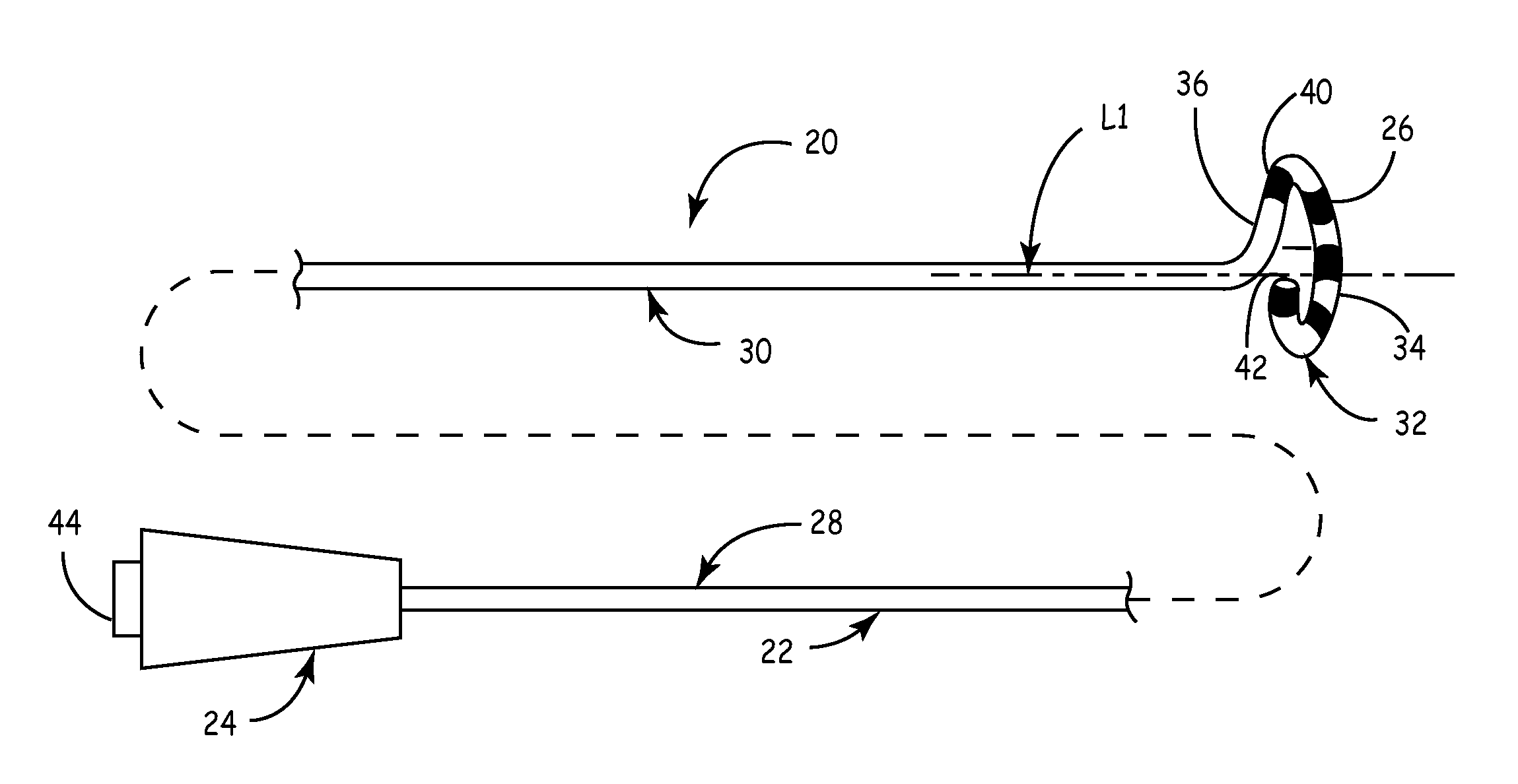
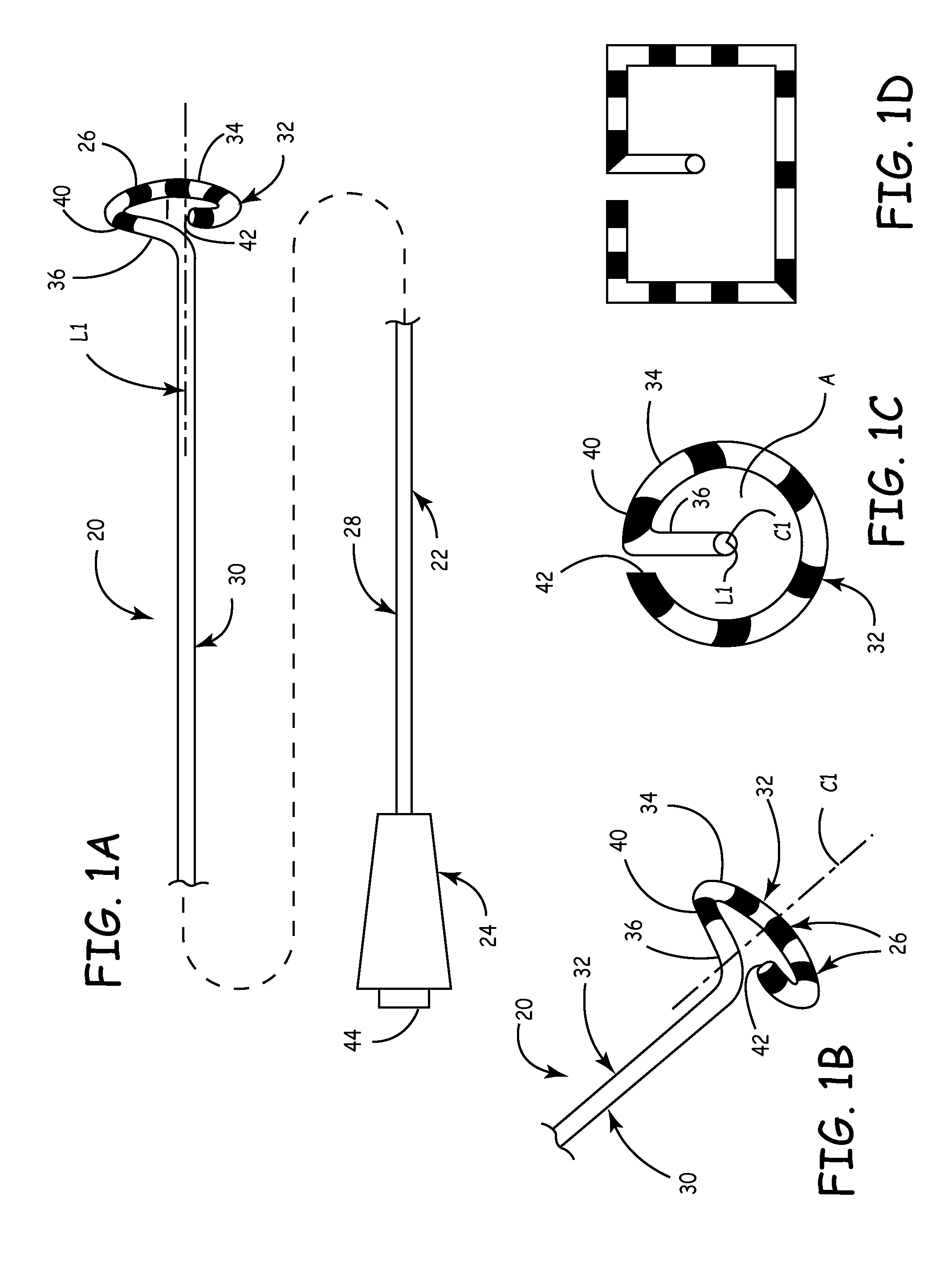
[0072]One preferred embodiment of a catheter assembly 20 in accordance with the present invention is shown in FIGS. 1A-1C. The catheter assembly 20 is comprised of a catheter body 22, a handle 24 and electrodes 26. As described in greater detail below, the catheter body 22 extends from the handle 24, and the electrodes 26 are disposed along a portion of the catheter body 22.

[0073]The catheter body 22 is defined by a proximal portion 28, an intermediate portion 30 and a distal portion 32, and includes a central lumen (not shown). Although not specifically shown, the catheter body may be configured for over-the-wire or rapid exchange applications. In one preferred embodiment, the proximal portion 28, the intermediate 30 and the distal portion 32 are integrally formed from a biocompatible material having requisite strength and flexibility for deployment within a heart. Appropriate materials are well known in the art and include polyamide.

[0074]The intermediate portion 30 extends from t...


PUM


Abstract

A catheter assembly for treatment of cardiac arrhythmia. The catheter assembly includes a catheter body and an ablative energy source. The catheter body includes a proximal portion, an intermediate portion, and a distal portion. The intermediate portion extends from the proximal portion and defines a longitudinal axis. The distal portion extends from the intermediate portion and includes an ablation section and a tip. The ablation section forms a loop defining a diameter greater than an outer dimension of a pulmonary vein ostium. The tip extends distally from the ablation section and is configured to locate a pulmonary vein. Finally, the ablative energy source is associated with the ablation section. With this configuration, upon activation of the energy source, the ablation section ablates a desired lesion pattern. In one preferred embodiment, the ablation section forms a distally decreasing radius helix, whereas the tip includes a relatively linear leader section. With this one preferred configuration, the tip readily locates a pulmonary vein and guides the ablation section to a seated relationship about a pulmonary vein ostium (or extra-ostial).

Description

CROSS-REFERENCE TO RELATED APPLICATIONS[0001]This application is a divisional of U.S. patent application Ser. No. 10 / 655,197, entitled “Ablation Catheter Assembly with Radially Decreased Helix and Method of Use”, filed Sep. 4, 2003, now allowed, which is a continuation-in-part of U.S. Pat. No. 6,702,811, entitled “Ablation Catheter Assembly and Method for Isolating a Pulmonary Vein, filed on May 3, 2001, which is a continuation-in-part of U.S. patent application Ser. No. 09 / 733,356, entitled “Ablation Catheter Assembly and Method for Isolating a Pulmonary Vein”, filed Dec. 8, 2000, now abandoned, which is a continuation in part of U.S. Pat. No. 6,325,797, entitled “Ablation Catheter and Method for Isolating a Pulmonary Vein”, filed Apr. 5, 1999, the contents of which are incorporated by reference herein it its entirety.BACKGROUND OF THE INVENTION[0002]The present invention relates to an ablation catheter for treatment of cardiac arrhythmia, for example atrial fibrillation. More part...

Claims


Application Information

Patent Timeline
Patent Type & Authority Applications(United States)
IPC IPC(8): A61B18/14A61B17/00
CPCA61B18/1492A61B2017/00044A61B2017/00243A61B2017/00867A61B2018/00065A61B2018/00214A61B2018/1472A61B2018/00351A61B2018/00375A61B2018/00404A61B2018/00898A61B2018/1407A61B2018/1435A61B2018/00267
Inventor STEWART, MARK T.SKARDA, JAMES R.
Owner MEDTRONIC INC
Why Eureka
Try Eureka