Medicine ejection device and controlling method thereof

a technology of ejection device and control method, which is applied in the direction of medical devices, inhalators, other medical devices, etc., can solve the problems of reducing volumetric capacity, requiring considerable power to deform flexible reservoirs, and high gas barrier properties, and achieves stable ejection and high sealability

Inactive Publication Date: 2010-08-19
CANON KK
View PDF6 Cites 14 Cited by
  • Summary
  • Abstract
  • Description
  • Claims
  • Application Information

AI Technical Summary

Benefits of technology

[0009]An object of the present invention is to provide a medicine ejection device which provides stable ejection even when a reservoir with high sealability is used and can eject an appropriate amount of medicine.

Problems solved by technology

However, when the reservoir stores a medicine in an amount of being inhaled multiple times, it is impossible to employ the structure of making the reservoir communicate with the atmosphere, because of needing to prevent a medicine remaining in the reservoir after the apparatus has been used once from changing its concentration and being denatured, so that the reservoir is required to have high gas barrier properties and sealability.
Even when the negative pressure in the reservoir increases in this way, a considerable power is required to deform the flexible reservoir with a force caused by the negative pressure, or reduce the volumetric capacity by sliding the rubber plug with respect to the glass container.
Because of this, an inhaler with the use of a conventional reservoir having high sealability decreases its ejection performance as the inhaler continues ejection, and sometimes could not eject a medicine though depending on a case.

Method used


Image

  • Medicine ejection device and controlling method thereof
  • Medicine ejection device and controlling method thereof
  • Medicine ejection device and controlling method thereof

Examples


embodiment 1

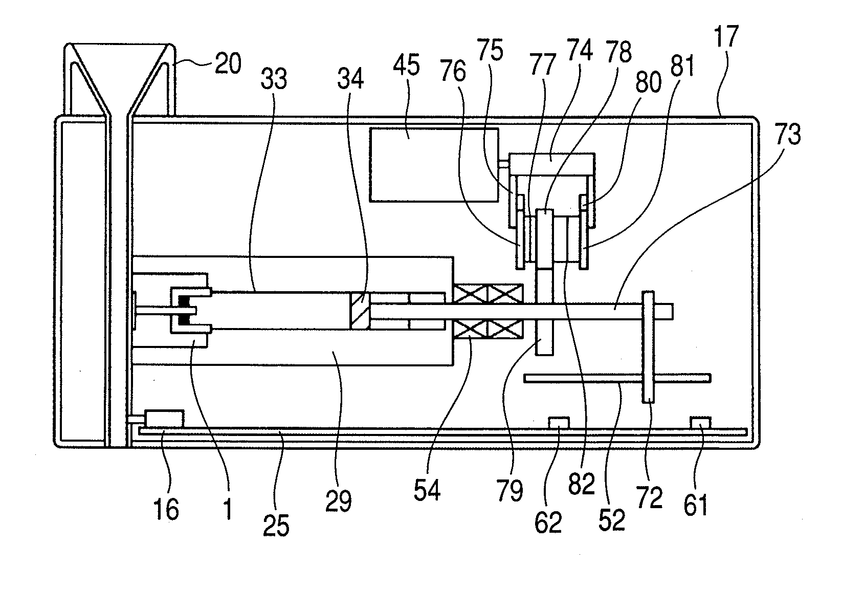
[0067]FIG. 8 illustrates a schematic sectional view of a medicine ejection device relating to a first embodiment of the present invention. In the present embodiment, an air compressor 21 which generates a compressed air was used for a pressure unit.

[0068]Compressors are largely classified into a turbo type and a volumetric type. The turbo type is mainly used when the pressure may be low and a large quantity of air is required. On the other hand, the volumetric type is used when a high pressure is required. The compressor used in the present embodiment was an air pump which is one of the volumetric types and adopts a diaphragm drive system of generating a compressed air by moving a diaphragm up and down with a torque of a motor. An air pump of the diaphragm drive system is comparatively small, and accordingly is suitable for an inhaler which is always carried.

[0069]The compressor 21 is connected with a rubber plug 34 of a movable wall and generates a pressure to be applied to the rub...

embodiment 2

[0085]FIG. 12 is a schematic sectional view of a medicine ejection device according to a second embodiment after a regulator 22 has been removed from Embodiment 1.

[0086]In the case of this embodiment, a pressure in an enclosed space behind a movable rubber plug 34, specifically a pressure in a tube 24 can be controlled in the same way as in Embodiment 1, by making the rotation speed of an air pump 21 variable based on a measured value by a pressure sensor 23. The pressure can be regulated by increasing the rotation speed of the air pump 21 so that the measured value by the pressure sensor matches a set value when the pressure is increased, and by decreasing the rotation speed when the pressure is decreased. The volume provided on a control substrate 25 can be automatically regulated with a control signal sent from a CPU. A flow of an example of using an inhaler is similar to that in Embodiment 1 except that the switching operation for a control valve of a regulator was replaced by a...

embodiment 3

[0087]FIG. 13 is a schematic sectional view of a medicine ejection device according to a third embodiment which employs an electric cylinder 41 for a pressure unit in place of an air pump. The electric cylinder 41 is a device which changes the volumetric capacity in a cylinder contained in the inner part, by rotating a ball screw or the like by the rotation of a built-in motor, and moving a direct-acting member connected to the ball screw. The medicine ejection device can easily detect the position because of containing an encoder and the like.

[0088]The compressed air generated by a volumetric change of the electric cylinder 41 is sent to a space behind a movable rubber plug 34 in a glass container 33. An internal pressure of an enclosed space which pressurizes the movable rubber plug 34 can be easily regulated, by controlling the switching of a solenoid valve 42 based on a pressure value of a pressure sensor 23. The user returns the position of the electric cylinder 41 to the start...


PUM


Abstract

The invention provides a medicine ejection device which provides stable ejection even when a reservoir with high sealability is used and can eject an appropriate amount of medicine. A medicine ejection portion 1 includes an ejection nozzle 1a for ejecting a medicine and an element 1b which generates energy for ejecting the medicine from the ejection nozzle 1a, and is connected to a medicine storing portion 2 for storing the medicine. The medicine storing portion 2 is blocked from the outside air except a path through the ejection nozzle 1a, so that when the medicine is ejected from the ejection nozzle 1a, a pressure difference is formed between the outside and the inside of the medicine storing portion 2. A pressure unit 3 which is a feature of the present invention pressurizes a movable wall 5 when ejecting a medicine, which is displaced so that the volumetric capacity of the medicine storing portion 2 decreases due to the pressure difference.

Description

TECHNICAL FIELD[0001]This invention relates to a medicine ejection device which is configured to allow a user to carry and use, and can be used in an inhaler for making a user inhale a medicine, and to a controlling method thereof.BACKGROUND ART[0002]An inhaler is developed which ejects micro-droplets of a medicine into an air flow path through which inhaled air via a mouthpiece flows by using an ejection principle in an ink jet system, and makes a user inhale (cf. Japanese Patent Application Laid-Open No. 2004-290593 and Japanese Patent Application Laid-Open No. 2004-283245). This type of an inhaler has an advantage of being capable of precisely spraying a specified amount of a medicine with a uniformized particle size.[0003]A basic configuration of such a medicine ejection device includes an ejection head in which an ejection energy generating element such as an exothermic element is arranged, and a reservoir for storing the medicine to be supplied to the ejection head therein. Wh...

Claims


Application Information

Patent Timeline
Patent Type & Authority Applications(United States)
IPC IPC(8): A61M15/00
CPCA61M15/02A61M2205/3306A61M2205/332A61M15/025A61M2205/3653A61M11/007A61M11/042A61M2205/3351A61M15/008A61M15/0081
Inventor IMAI, MITSURU
Owner CANON KK
Why Eureka
Try Eureka