Light emitting device

Inactive Publication Date: 2010-08-19
EVERLIGHT ELECTRONICS
View PDF27 Cites 16 Cited by
  • Summary
  • Abstract
  • Description
  • Claims
  • Application Information

AI Technical Summary

Benefits of technology

[0008]An embodiment of the invention provides a light emitting device, which includes a t

Problems solved by technology

In other words, the light beam generated by the LED has high directivity, and thus may result in unfavorable light uniformity and glares that would cause discomfort of the user.
The size of the whole LED illumination device is increased as a consequence, which causes inconvenien

Method used


Image

  • Light emitting device
  • Light emitting device
  • Light emitting device

Examples


Example

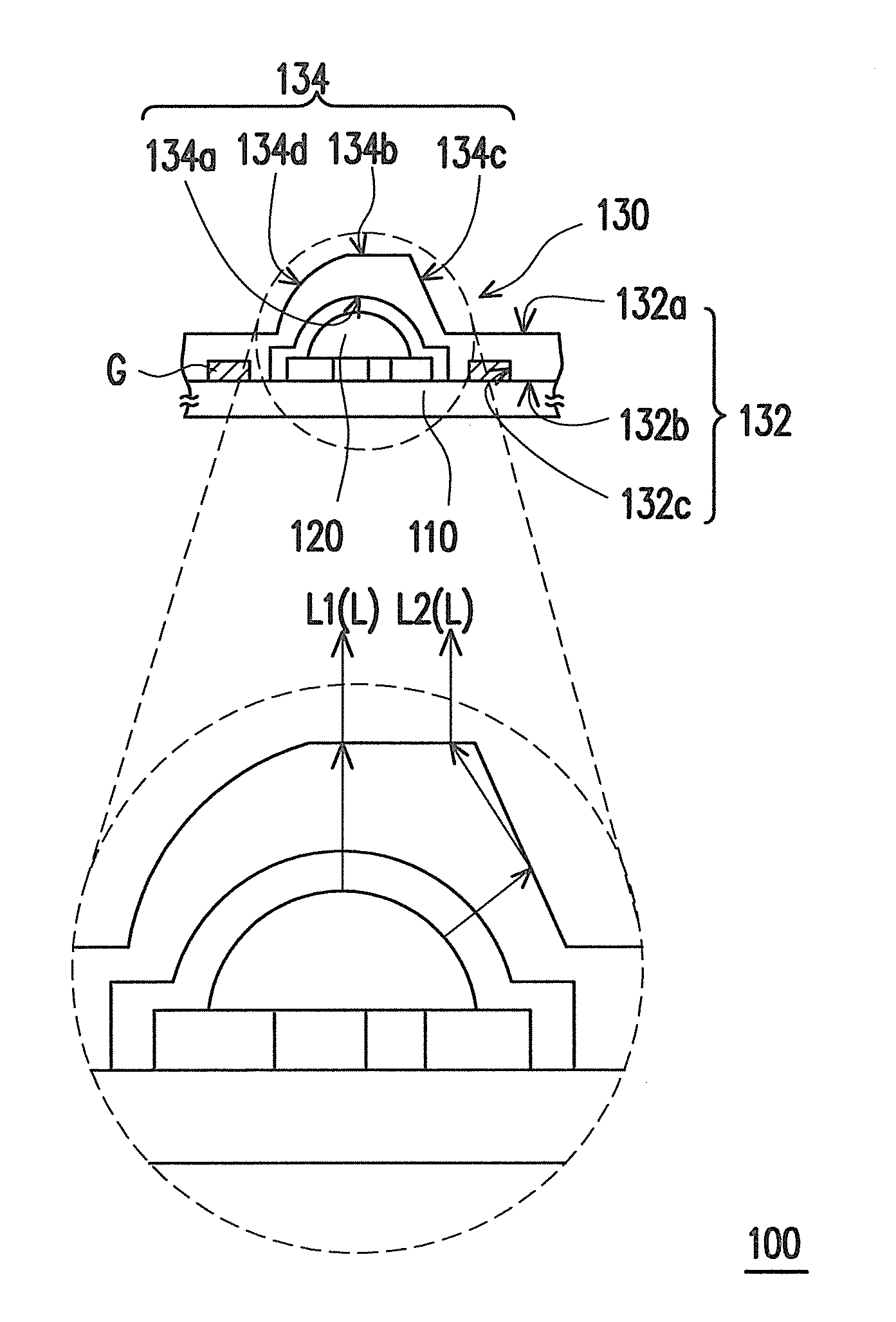
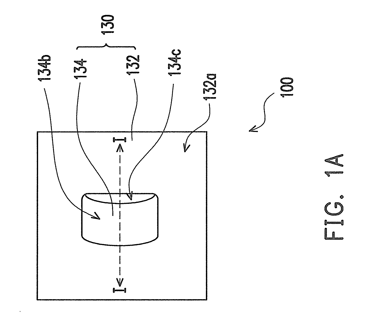
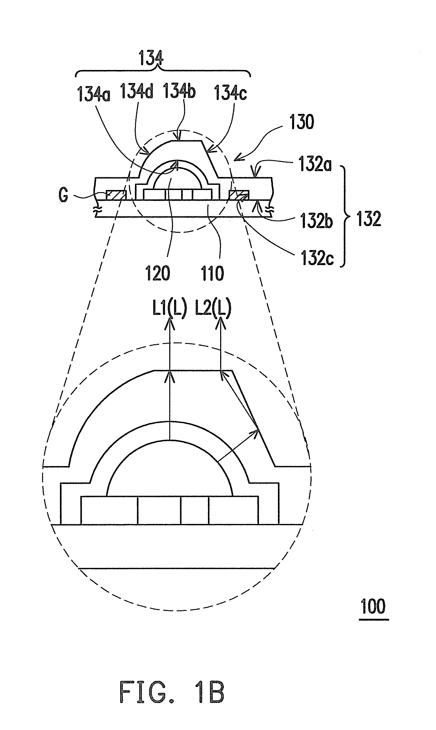
[0054]FIG. 1A is a schematic top view of a light emitting device according to an embodiment of the invention. FIG. 1B is a schematic side view taken along line I-I in FIG. 1A. FIG. 1C is a schematic back-side view of the transparent plate depicted in FIG. 1A. Referring to FIG. 1A, FIG. 1B, and FIG. 1C simultaneously, in the present embodiment, a light emitting device 100 includes a carrier 110, a light emitting element 120, and a transparent plate 130.

[0055]In details, the light emitting element 120 is disposed and electrically connected to the carrier 110. In the present embodiment, the light emitting element 120 is a light emitting diode (LED), and more specifically, this LED is a surface mount device (SMD) LED.

[0056]The transparent plate 130 is disposed on the carrier 110 and covers the light emitting element 120. Moreover, the transparent plate 130 includes a flat-portion 132 and a lens-portion 134, which is connected to the flat-portion 132. The flat-portion 132 has an upper su...


PUM


Abstract

A light emitting device includes a carrier, a light emitting element disposed and electrically connected to the carrier, and a transparent plate disposed on the carrier and including a flat-portion and a lens-portion. The lens-portion covers the light emitting element and has a light incident surface, a light emitting surface, a first side surface and a second side surface. The light emitting element is adapted to emit a beam. A first partial beam of the beam passes through the light incident surface and emerges from the light emitting surface. A second partial beam of the beam passes through the light incident surface and is transmitted to the first side surface or the second side surface, and the first side surface or the second side surface reflects at least a part of the second partial beam of the beam which then emerges from the light emitting surface.

Description

CROSS-REFERENCE TO RELATED APPLICATION[0001]This application is a continuation-in-part application of and claims the priority benefit of Ser. No. 12 / 610,371, filed on Nov. 2, 2009, now pending, which claims the priority benefit of Taiwan application serial no. 98105180, filed on Feb. 18, 2009. This application also claims the priority benefit of Taiwan application serial no. 98137149 filed on Nov. 2, 2009. The entirety of each of the above-mentioned patent applications is hereby incorporated by reference herein and made a part of this specification.BACKGROUND OF THE INVENTION[0002]1. Field of the Invention[0003]The invention relates to a light emitting device, and more particularly, to a light emitting device with a better light emitting uniformity and efficiency.[0004]2. Description of Related Art[0005]A light emitting diode (LED) is a light emitting element constituted by a semiconductor material having group III-V elements. The LED has advantages such as long service life, small ...

Claims


Application Information

Patent Timeline
IPC IPC(8): H01L33/08
CPCF21K9/00F21V5/007F21V7/0083F21V13/02G02B19/0061F21Y2105/001G02B19/0066G02B19/0028F21Y2101/02F21Y2105/10F21Y2115/10F21K9/69
Inventor CHIANG, JEN-TALIANG, CHIA-HAOTSAI, HSIN-CHANG
Owner EVERLIGHT ELECTRONICS
Why Eureka
Try Eureka