GPS antenna array and system for adaptively suppressing multiple interfering signals in azimuth and elevation

a technology of antenna array and antenna array, applied in the field of antennas, can solve problems such as serious errors in position measurement, accuracy degradation, and errors in the position determined by the receiver

Active Publication Date: 2010-08-19
BAE SYST INFORMATION & ELECTRONICS SYST INTERGRATION INC
View PDF11 Cites 51 Cited by
  • Summary
  • Abstract
  • Description
  • Claims
  • Application Information

AI Technical Summary

Benefits of technology

[0027]In the disclosed embodiment, the adaptive processor combines the reference and selected low-elevation auxiliary beams adaptively with one another to produce a null in the reception pattern of the antenna system at one or more determined angles in azimuth and in elevation, to suppress multiple interfering signals without degrading authentic signals at other angles of the reception pattern.

Problems solved by technology

The calculated distance to the transmitting satellite based on a reflected GPS signal will be greater than the actual line of sight distance, thus causing error in the position determined by the receiver.
Other degrading factors may include receiver clock errors, orbital (ephemeris) errors, number of satellites visible (the fewer satellites in view, the lower the accuracy), and the relative positions of the satellites at any given time (accuracy degrades when the satellites are spaced angularly close to one another as seen from the receiver).
Thus, it will be understood that ignoring variations in the phase center of a GPS receiving antenna can lead to serious errors in position measurement.
As mentioned, GPS reference antennas are subject to unintentional (lateral and sea multipath) and intentional (jamming) interference which can adversely affect approach and landing guidance.
In DGPS applications, the known techniques can act to degrade the overall precision of the system, however.
Also, if the array dimensions are too small, it becomes difficult to break the null sharply; that is, the reception pattern stays attenuated over a relatively large angle away from the desired angle of the null.
In the event multiple interfering signals are detected at different elevation angles, the null may be steered to a determined angle between the interferers, but such a solution is not effective to eliminate all potential errors attributable to the interferers.
More complex threats in the form of multiple jammers each at differing elevation angles of arrival may exist, however.

Method used


Image

  • GPS antenna array and system for adaptively suppressing multiple interfering signals in azimuth and elevation
  • GPS antenna array and system for adaptively suppressing multiple interfering signals in azimuth and elevation
  • GPS antenna array and system for adaptively suppressing multiple interfering signals in azimuth and elevation

Examples


Embodiment Construction

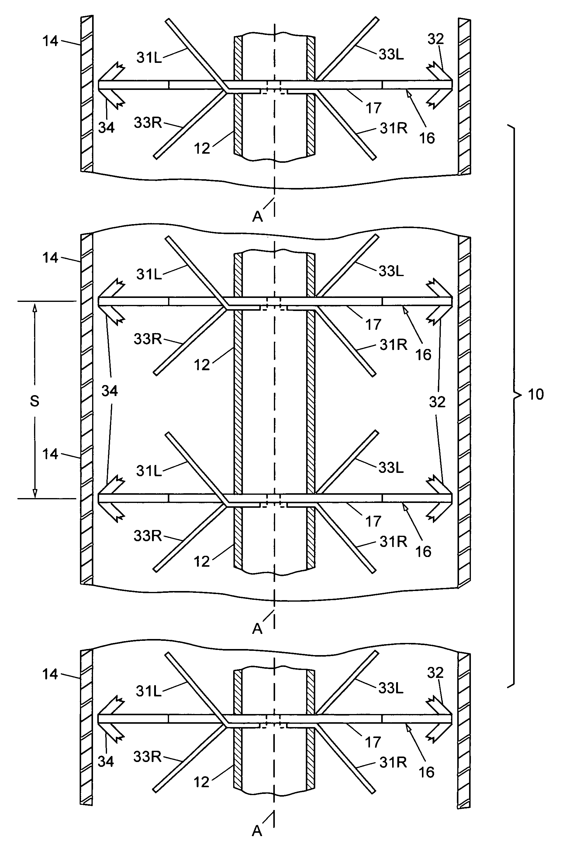
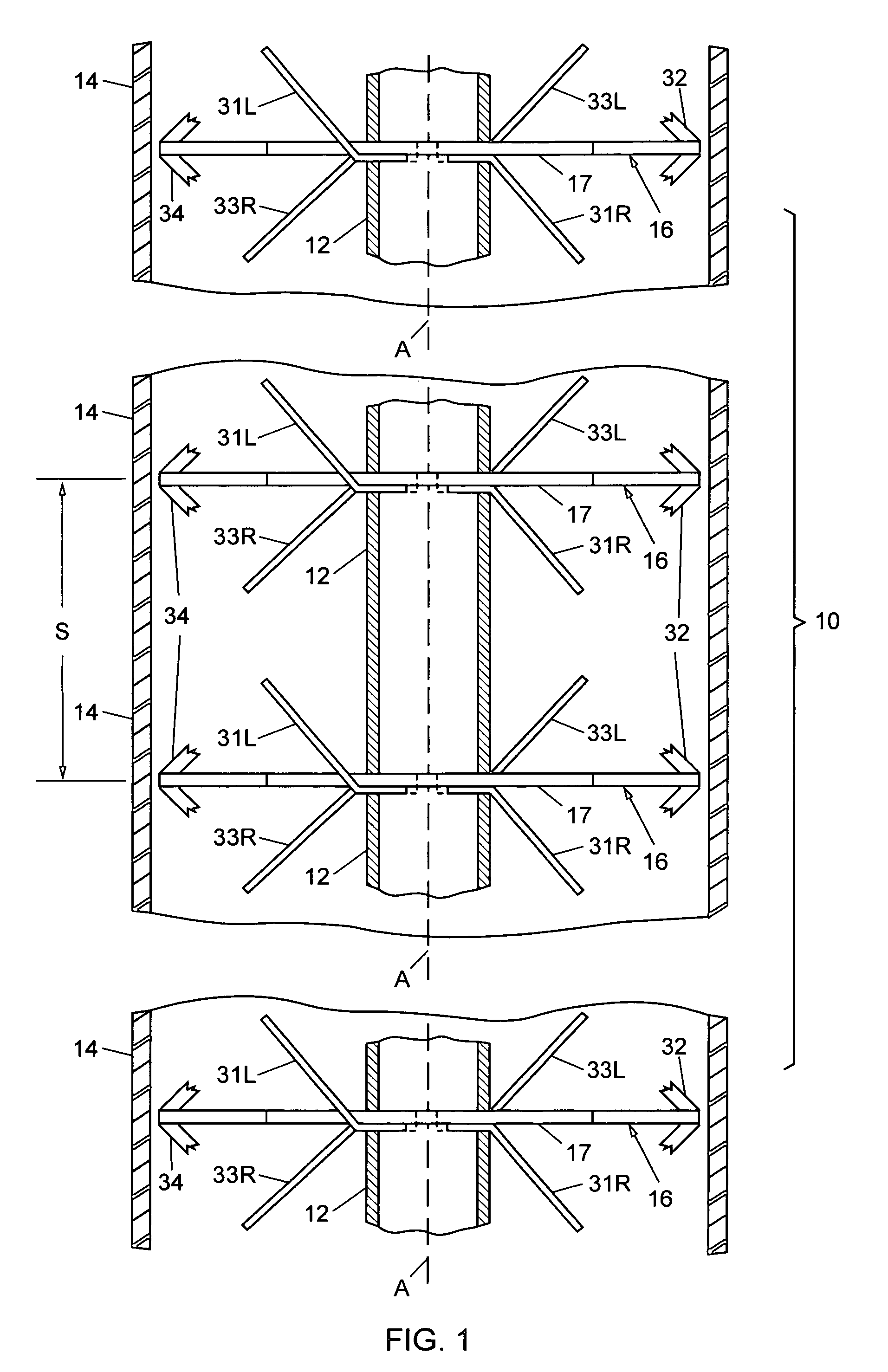
[0046]FIG. 1 is a partial view of an antenna 10 according to the invention. In the disclosed embodiment, antenna 10 is constructed and arranged for use as a reference antenna array in a differential global positioning system (DGPS). The antenna 10 includes a mast 12 having an axis A, and the mast is arranged to be fixed at one or more positions (not shown in FIG. 1) with respect to a surrounding ground area so that it can extend vertically above the area. The ground area may be located, for example, in the vicinity of a ground airport runway or a landing zone on an aircraft carrier.

[0047]The antenna 10 has an exterior protective shell or radome 14 which can be, e.g., circularly cylindrical in form with an axis that coincides with the axis A of the mast 12. Preferably, the material (typically a fiberglass reinforced plastics) and wall thickness of the radome 14 should have negligible, if any, effect on the amplitude and phase of GPS signals passing through the radome at all angles of...


PUM


Abstract

An antenna system has N antenna units stacked on a mast. Each unit has elements for responding to, e.g., GPS signals, and a phasing network that produces mutually orthogonal primary and auxiliary pattern modes at corresponding mode ports of the unit. A number of power dividers are each associated with a different mode, and each divider has N input ports coupled to the associated mode port of a corresponding antenna unit. The power divider associated with the primary pattern mode produces a reference beam and an auxiliary beam, and remaining power dividers produce different auxiliary beams. All beams have approximately both a common phase center and a common group delay center. An adaptive processor combines the reference and selected auxiliary beams to obtain a composite antenna reception pattern in which nulls are inserted at certain angles to suppress interfering signals, without degrading authentic signals arriving at other angles.

Description

BACKGROUND OF THE INVENTION[0001]1. Field of the Invention[0002]This invention relates to antennas, particularly a GPS antenna operative to null or suppress reception of interfering signals.[0003]2. Discussion of the Known Art[0004]The Global Positioning System (GPS) is a navigation system featuring a constellation of 24 satellites that traverse six circular orbits around the Earth twice a day, with four satellites in each orbit. The satellites transmit coded L-band microwave radio frequency (RF) signals, and are always positioned so that signals from at least four of the satellites can be received at any point on Earth.[0005]Specifically, each GPS satellite presently transmits its signals using two RF carrier frequencies, viz., 1575.42 MHZ (referred to as “L1”) and 1227.60 MHZ (“L2”). A third frequency of 1176.45 MHZ (“L5”) has also been allocated for civilian use in 2009. The L1 signal is modulated by two different spread spectrum codes, namely, an unclassified coarse acquisition ...

Claims


Application Information

Patent Timeline
Patent Type & Authority Applications(United States)
IPC IPC(8): G01S5/14G01S1/00H01Q21/00H01Q9/16
CPCG01S19/21G01S19/35H01Q1/38H01Q3/2617H01Q25/00H01Q9/40H01Q9/42H01Q21/293H01Q9/16
Inventor LACKEY, RAYMOND J.
Owner BAE SYST INFORMATION & ELECTRONICS SYST INTERGRATION INC
Why Eureka
Try Eureka