Footwear with embedded tracking device and method of manufacture

a tracking device and footwear technology, applied in the field of personal tracking devices, can solve the problems of incorporating a personal tracking device into footwear, the location of the tracking device, and the general size and cost of the antenna, and achieve the effect of facilitating the connection to the battery and facilitating the insertion of a memory devi

Inactive Publication Date: 2007-08-23
GLOBAL TREK XPLORATION CORP
View PDF10 Cites 56 Cited by
  • Summary
  • Abstract
  • Description
  • Claims
  • Application Information

AI Technical Summary

Benefits of technology

[0014] In the example embodiment, the wireless communication device and the location determining device are encapsulated in a waterproof material (e.g., a polyamide resin). The encapsulating waterproof material defines a slot to facilitate the insertion of a memory device (e.g., a Subscriber Identification Module or SIM card) to uniquely identify the wireless communication device. The slot is sealed (e.g., by adhesive, removable plug, etc.) after the memory device is inserted.
[0015] The encapsulating material also defines

Problems solved by technology

However, there are many obstacles to incorporating a personal tracking device into footwear, while maintaining the comfort, appearance, and affordability of the footwear.
One issue that must be addressed is the location of the tracking device.
As the sensitivity requirement increases, so generally does the size and cost of the antenna.
Additional amplifiers may also be required, which further increases the cost as well as the power consumption of the unit.
Positioning the tracking device in the footwear upper can also be problematic.
Such an expansion of the upper would almost certainly be noticeable and likely be unacceptable from an appearance standpoint.
Therefore, any device of significant size incorporated in the upper might be felt by the wearer, adversely affecting the comfort of the footwear.
Another problem that must be addressed is that the circuitry of the tracking device must be protected from moisture, contamination, and damage, particularly where the footwear is designed for active children and/or outdoor activities such as hunting, wild

Method used


Image

  • Footwear with embedded tracking device and method of manufacture
  • Footwear with embedded tracking device and method of manufacture
  • Footwear with embedded tracking device and method of manufacture

Examples


Embodiment Construction

[0032] The present invention overcomes the problems associated with the prior art, by providing footwear with an embedded tracking device. In the following description, numerous specific details are set forth (e.g., particular electronic components) in order to provide a thorough understanding of the invention. Those skilled in the art will recognize, however, that the invention may be practiced apart from these specific details. In other instances, details of well known footwear manufacturing and electronics assembly practices and components have been omitted, so as not to unnecessarily obscure the present invention.

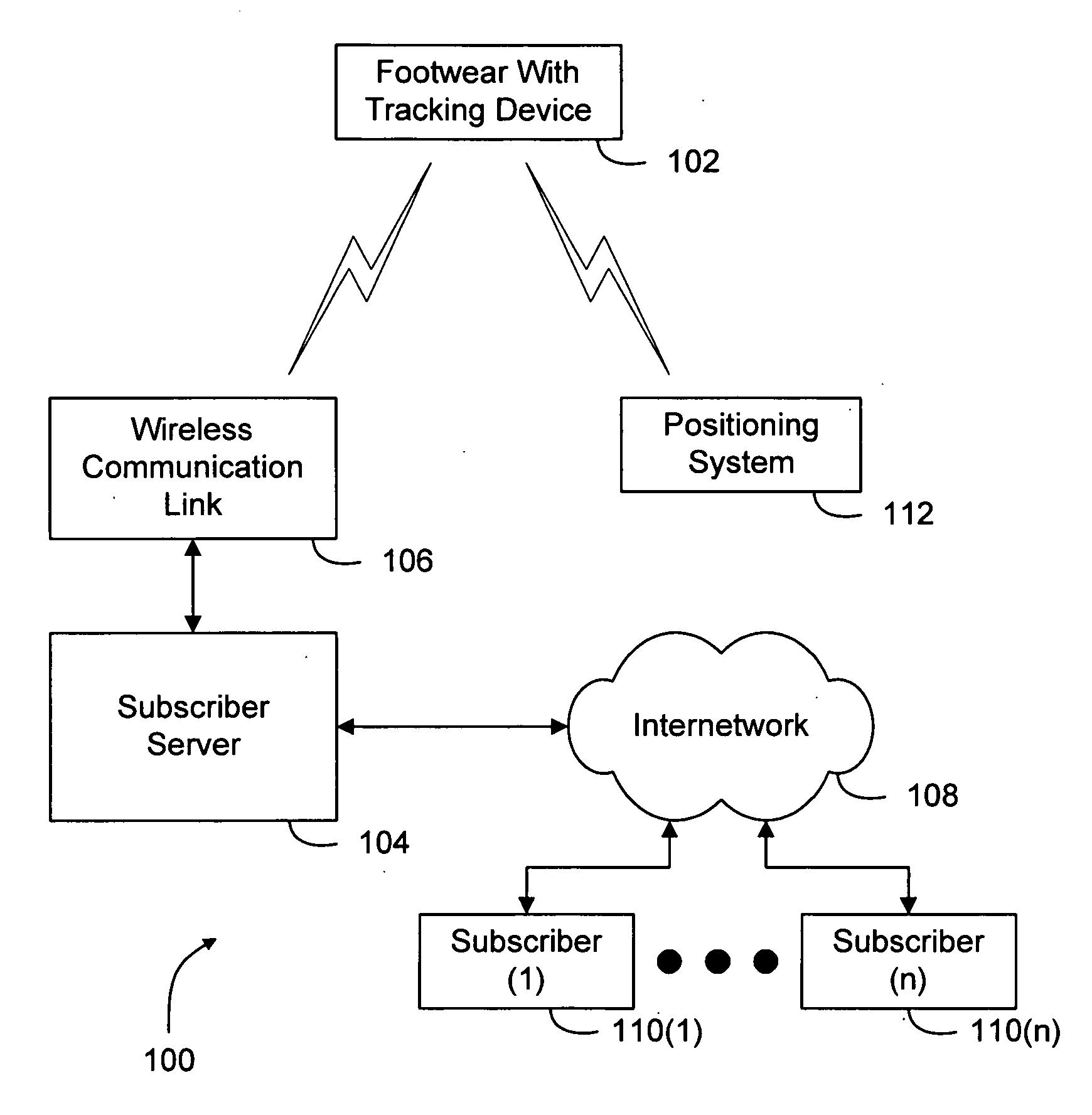
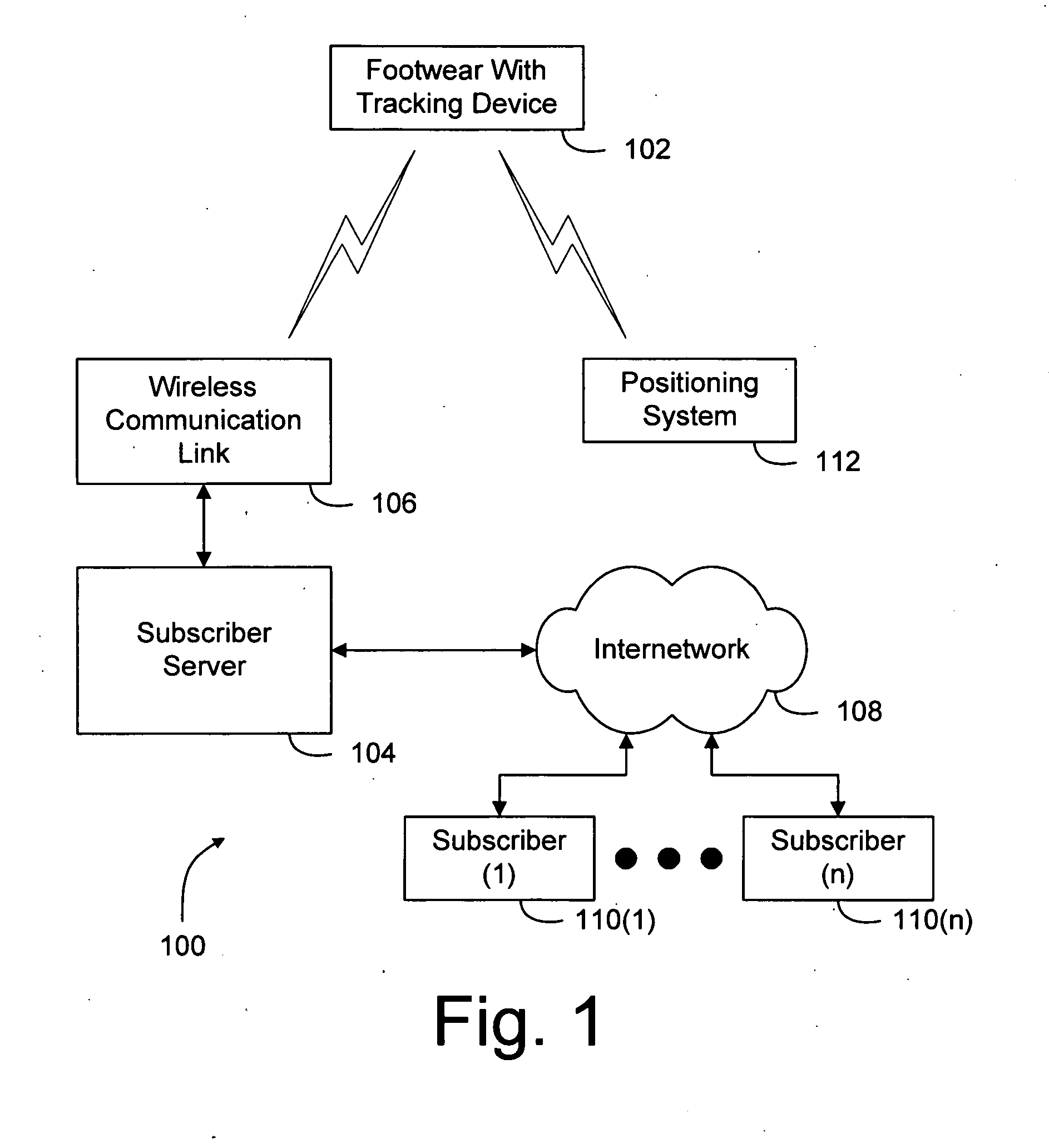
[0033]FIG. 1 is a block diagram of a tracking system 100 including the footwear 102 of the present invention. Tracking system 100 further includes a subscriber server 104, a wireless communication link 106, an internetwork 108, one or more subscribers 110(1-n), and a positioning system 112.

[0034] Footwear 102 includes a tracking device that communicates wirelessly wit...


PUM


Abstract

Footwear with an embedded tracking device includes a sole and an upper. The tracking device is disposed in a cavity formed in the top surface of the sole. A wireless communication antenna and/or a location signal antenna is disposed on the upper. The antenna(s) is/are connected to the tracking device via a flexible circuit substrate. In a particular embodiment, the location signal antenna is a passive, directional GPS antenna supported in an upwardly facing position in the heel portion of the upper. A method for manufacturing footwear with an embedded tracking device is also disclosed. The method includes providing a footwear upper, incorporating an antenna in the footwear upper, providing a footwear sole, fixing the footwear upper to the footwear sole, incorporating a tracking device into the footwear sole, and connecting the tracking device to the antenna.

Description

BACKGROUND OF THE INVENTION [0001] 1. Field of the Invention [0002] This invention relates generally to personal tracking devices, and more particularly to a personal tracking device embedded in footwear. [0003] 2. Description of the Background Art [0004] Personal tracking devices are known in the art. One possibly desirable means of carrying a personal tracking device is to incorporate the personal tracking device into footwear. However, there are many obstacles to incorporating a personal tracking device into footwear, while maintaining the comfort, appearance, and affordability of the footwear. [0005] One issue that must be addressed is the location of the tracking device. If the tracking device (including the antenna) is located in the sole of the footwear, the satellite location determination signals are shielded from the unit by the wearers foot, and so a relatively sensitive antenna is required. As the sensitivity requirement increases, so generally does the size and cost of ...

Claims


Application Information

Patent Timeline
IPC IPC(8): A43B5/00G01S19/19
CPCA43B3/0005A43B13/00A43B7/00A43B5/00H05K1/147H05K3/284H05K2201/10037H05K2201/10098H05K2201/10189A43B3/34
Inventor BERTAGNA, PATRICK E.DAVIS, RALPH H.WALSH, CHRISTOPHER M.SCHILAWSKI, GREGG S.COHEN, JAMES H.LIM, DONGEUNPROVENZANO, GREGORY J.STRICKER, ALEXANDER GILDEA
Owner GLOBAL TREK XPLORATION CORP
Why Eureka
Try Eureka