Battery pack of large capacity

a battery pack and large capacity technology, applied in the direction of batteries, cell components, jackets/cases materials, etc., can solve the problems of high manufacturing cost of hard battery packs, low compatibility of hard batteries with external devices, and uneven surface of hard batteries, so as to improve the safety of batteries.

Active Publication Date: 2010-08-19
LG ENERGY SOLUTION LTD
View PDF6 Cites 15 Cited by
  • Summary
  • Abstract
  • Description
  • Claims
  • Application Information

AI Technical Summary

Benefits of technology

[0019]Specifically, it is an object of the present invention to provide a battery pack having a desired strength obtained by a specific coupling structure using a frame member without using a conventional pack sheathing member, such as a box-shaped case, and a relatively large capacity at the same standardization level.
[0048]The two metal sheets of the safety member may be made of the same material as current collectors constituting the cathodes and anodes of the electrode assembly. For example, sheet A may be made of aluminum foil having no active material applied thereto, and sheet B may be made of copper foil having no active material applied thereto. Consequently, when a needle-shaped object presses against the electrode assembly or penetrates the electrode assembly, the metal sheets of the safety member according to the present invention, which have no active material applied thereto and are electrically connected to the cathode terminal and the anode terminal, are brought into contact with each other first to induce a micro short circuit, thereby improving the safety of the battery.

Problems solved by technology

As a result, the manufacturing costs of the hard battery pack are high, and, furthermore, the hard battery pack has low compatibility with the external devices.
In the battery pack with the above-stated construction, however, the outermost surface of the battery pack is not covered by an additional sheathing member, with the result that the bent parts and the joint parts of the packing members are exposed to the outside, and therefore, the surface of the battery pack is not smooth.
This problem may serve as a main cause of inflicting injury on an engineer or a user and to threaten the security of the engineer or the user during the manufacture or use of the battery pack.
In addition, the external appearance of the battery cell, mounted in the battery pack, is maintained by the frame member, and the strength of the battery cell is supplemented by the frame member; however, the top and bottom of the battery cell, which is not protected by the frame member, are covered by only the packing members, which are mechanically weak.
Consequently, it is not possible to achieve a desired strength.
As a result, the lithium secondary battery may be heated or explode due to the overcharge of the battery, the overcurrent in the battery, or other physical external impacts.
That is, the safety of the lithium secondary battery is very low.
The welding or soldering process must be carried out very precisely due to the small structure of the secondary battery, and therefore, a possibility of battery defect is increased.
Furthermore, the addition of the above-described process increases the manufacturing costs of products.

Method used


Image

  • Battery pack of large capacity
  • Battery pack of large capacity
  • Battery pack of large capacity

Examples


Embodiment Construction

[0054]Now, a preferred embodiment of the present invention will be described in detail with reference to the accompanying drawings. It should be noted, however, that the scope of the present invention is not limited by the illustrated embodiment.

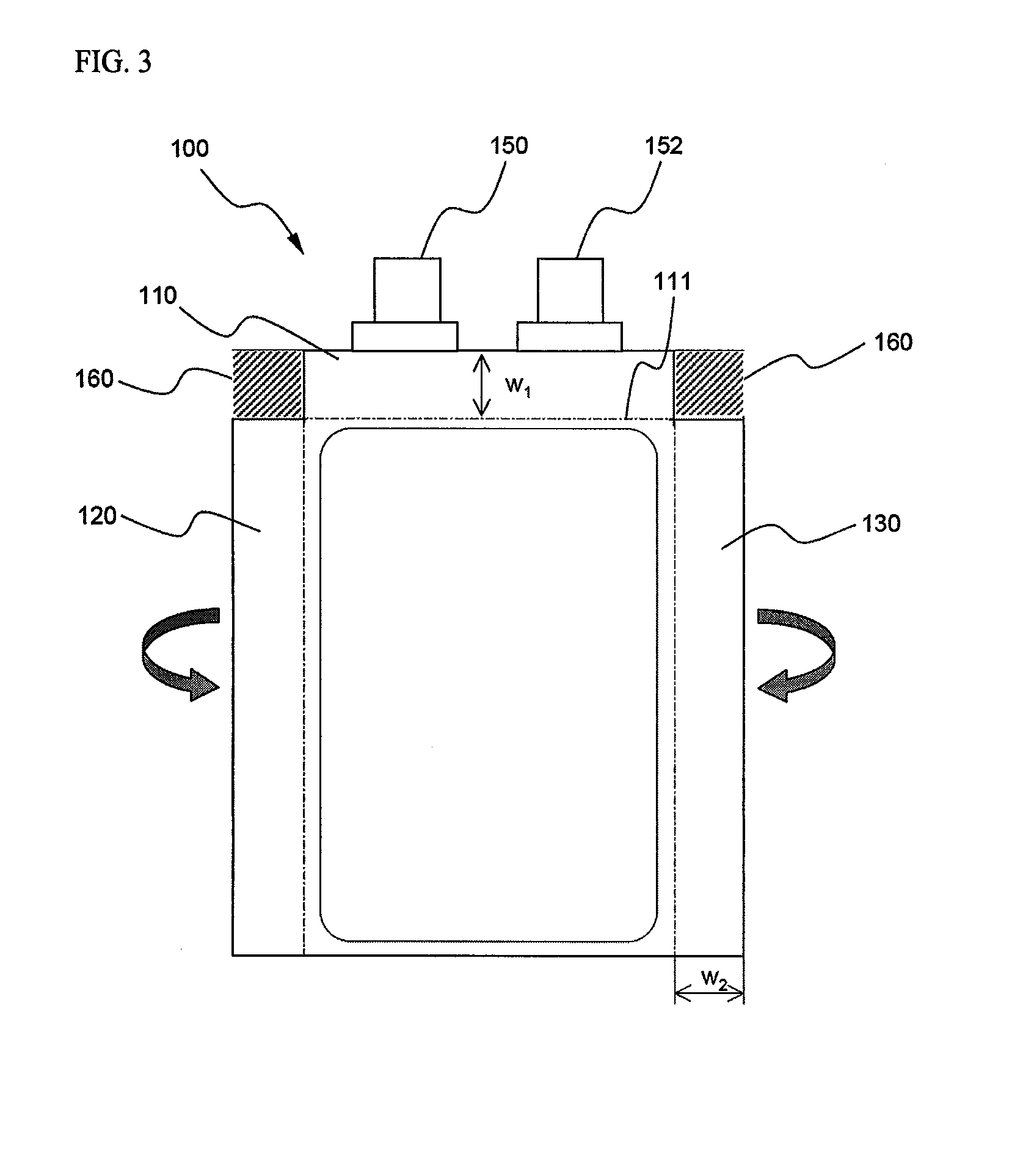
[0055]FIG. 3 is a front view illustrating an exemplary pouch-shaped battery that is preferably usable in a battery pack according to a preferred embodiment of the present invention. The pouch-shaped battery of FIG. 3 is approximately identical to the conventional pouch-shaped battery, which is being generally used, and therefore, only the characteristics of the present invention will be described hereinafter.

[0056]When the upper end and opposite sides of the pouch-shaped battery 100, while an electrode assembly is mounted in a battery case of the pouch-shaped battery 100, sealing portions 110, 120, and 130 are formed at the upper end and opposite sides of the pouch-shaped battery 100. According to the present invention, the upper end sealing...


PUM

PropertyMeasurementUnit
thicknessaaaaaaaaaa
thicknessaaaaaaaaaa
piercing forceaaaaaaaaaa

Abstract

Disclosed herein is a battery pack including a battery cell, having an electrode assembly mounted in a pouch-shaped battery case made of a laminate sheet including a metal layer and a resin layer and is sealed by thermal welding, mounted in a pack case, wherein the pack case includes a frame member constructed in a structure in which a receiving part for receiving the battery cell is open, opposite side sealing portions of the battery cell are mounted to the frame member such that the opposite side sealing portions cover the opposite sides of the frame member, and a sheathing film is applied to the outer surface of the frame member, to which the battery cell is mounted.

Description

FIELD OF THE INVENTION[0001]The present invention relates to a battery pack of large capacity, and, more particularly, to a battery pack including a battery cell, which has an electrode assembly mounted in a pouch-shaped battery case made of a laminate sheet including a metal layer and a resin layer and is sealed by thermal welding, mounted in a pack case, wherein the pack case includes a frame member constructed in a structure in which a receiving part for receiving the battery cell is open, opposite side sealing portions of the battery cell are mounted to the frame member such that the opposite side sealing portions cover the opposite sides of the frame member, and a sheathing film is applied to the outer surface of the frame member, to which the battery cell is mounted.BACKGROUND OF THE INVENTION[0002]As mobile devices have been increasingly developed, and the demand of such mobile devices has increased, the demand of secondary batteries has also sharply increased as an energy so...

Claims


Application Information

Patent Timeline
Patent Type & Authority Applications(United States)
IPC IPC(8): H01M2/08H01M50/119H01M50/121H01M50/124H01M50/133H01M50/178H01M50/55H01M50/553
CPCH01M2/0275H01M2/0287H01M2220/30H01M2/30H01M2/1066Y02E60/10H01M50/124H01M50/133H01M50/121H01M50/55H01M50/178H01M50/553H01M50/119
Inventor AHN, CHANG BUMLEE, HYANG MOKCHOI, BYUNGJINJANG, JUN HWANYUN, HYUNG KUHWANG, SUNG-MINJUNG, HYUN-CHUL
Owner LG ENERGY SOLUTION LTD
Why Eureka
Try Eureka